background image

 Multi Format LCD Monitor   9

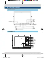
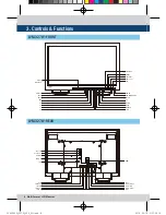
3. Controls & Functions

FRONT


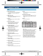
[STATUS INDICATOR] Lamp 

- Used to display the current input mode.  

- Input Mode

   VIDEO : COMPOSITE 1/2/3

   S-VID  : S-VIDEO

   COMP : COMPONENT

   RGB    : RGB 

   DVI-A  : DVI ANALOG

   DVI-D  : DVI DIGITAL

   HDMI   : HDMI

   SDI-A   : SDI-A

   SDI-B   : SDI-B

- In PBP mode, each screen’s input modes are  

 displayed.

  Ex) When SDI-A input and COMPOSITE 1    

  input are selected for left screen and right  

  screen respectively, SDI-A lamp and VIDEO  

  lamp will light.   


[ANALOG] Button/Lamp

- Used to select the desired Analog input.    

  Press the button to activate the analog input  

  menu-selection, then use the [UP]/[DOWN]  

  buttons to select desired input.
* See section “6. Other Functions [1]ANALOG”  

  page for more information.


[SDI-A] Button/Lamp

- Used when SDI-A INPUT is selected. 


[SDI-B] Button/Lamp

- Used when SDI-B INPUT is selected. 


[PBP] Button/Lamp

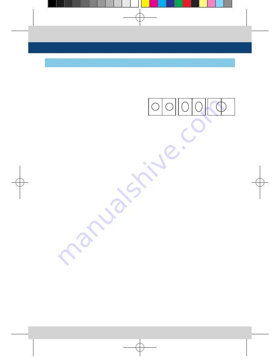
- Used to select PBP(Picture-by-Picture)  


 function.

- Selects the order of operation: mode 1 ->

  mode 2 -> mode 3 in sequence.

* MODE 1 : Two images are displayed in the  

  center of the monitor with maintain their   

  screen ratio.
* MODE 2 : Two images are displayed with fill  

  full in the monitor.
* MODE 3 : Left input signal displayed in the  

  left hand side of the monitor, right input    

  signal displays in the right hand side monitor 

  with maintain their screen raitio.


[F1][F2][F3][F4] Button/Lamp

- These functions buttons are used to activate

  the feature selected in “System- KEY  


  FUNCTION 1/2/3/4 ” menu. 

- [F1] button is used to select a screen in PBP  

 mode.

* See the “5. MENU Contents -> [9] SYSTEM   

  Page” for more information. 


[SCAN] Button/Lamp

- Used to change the Scan mode. The mode is  

  changed as the following sequence :

  OVER SCAN -> ZERO SCAN -> UNDER SCAN  

  -> 2:1 SCAN -> 1:1 SCAN -> FIT WIDTH ->    

  ZOOM(PBP 16:9 Mode)
* See the “6. Other Functions -> [4] SCAN”    

  page for more information. 


[MARKER] Button/Lamp

- Used to activate or inactivate the marker.   

  The desired aspect ratio can be displayed on  

  the screen properly when the type of marker  

  selected from the main menu.

MODE1

MODE2

MODE 3

LVM-245W_327W_V2.0_EN.indd   9

2014-04-10   오후 2:01:55

Summary of Contents for LVM-245W

Page 1: ...MultiFormatBroadcast LCD Monitor Operation Manual_v2 0 LVM 245W LVM 327W LVM 245W_327W_V2 0_EN indd 1 2014 04 10 2 01 53...

Page 2: ...LVM 245W_327W_V2 0_EN indd 2 2014 04 10 2 01 53...

Page 3: ...mful interference to radio communications Operation of this equipment in a residential to correct the interference at his own expense CAUTION Change or modifications not expressly approved by the manu...

Page 4: ...repair the product yourself Removing covers can expose you to high voltage and other dangerous conditions Request a qualified service person to perform servicing If any of the following conditions oc...

Page 5: ...urer s instruction Use only the mounting hardware recommended by the manufacturer When relocating the product placed on a cart it must be moved with the utmost care Sudden stops excessive force and un...

Page 6: ...ion without additional peripheral equipment attached to the unit DVI HDMI HDCP function built in DVI Analog DVI Digital and HDMI HDCP Inputs are available without the need of extra accessories RS 422...

Page 7: ...I B PBP F1 F2 F3 F4 POWER POWER INDICATOR ENTER UP DOWN APERTURE BRIGHT CONTRAST AUDIO OUT USB MENU MARKER SCAN REMOTE RS 422 IN RS 422 OUT RS 232 HDMI AUDIO IN DVI I CVBS1 Y G S Y CVBS2 Pb B CVBS3 Pr...

Page 8: ...POWER INDICATOR ENTER UP DOWN APERTURE BRIGHT CONTRAST AUDIO OUT USB MENU MARKER SCAN STATUS INDICATOR ANALOG RS 422 IN RS 422 OUT REMOTE AC IN SDI B OUT SDI B IN SDI A OUT SDI A IN RS 232 CVBS1 Y G S...

Page 9: ...peration mode 1 mode 2 mode 3 in sequence MODE 1 Two images are displayed in the center of the monitor with maintain their screen ratio MODE 2 Two images are displayed with fill full in the monitor MO...

Page 10: ...trol value range 100 100 CONTRAST Knob Used to adjust the contrast Control value range 100 100 AUDIO OUT PHONE JACK Selects the Left Right Audio disembedded signal output or HDMI input signal or exter...

Page 11: ...2 CVBS2 Pb B NoCon 3 CVBS3 Pr R C RS422 IN OUT RJ 45 Used to control the monitor with protocol provided by TVLogic or to support TSL protocol REMOTE RJ 45 Provides connection to control equipment for...

Page 12: ...he ENTER button at PAGE I PAGE II 3 Menu Control Sequence 4 Menu Tree Adjustment LVM 327W SDI A PAGE I PAGE II BRIGHT CONTRAST CHROMA PHASE APERTURE NTSC SETUP VGA H POSITION VGA V POSITION 0 0 0 0 0...

Page 13: ...TEMP GAIN RED GAIN GREEN GAIN BLUE BIAS RED BIAS GREEN BIAS BLUE BACK LIGHT COLOR SPACE GAMMA CURVE DISPLAY HD DISPLAY MODE TIME CODE ENABLE ORBITER CIRCUIT CLOSED CAPTION 608 CAPTION SELECT 708 SERVI...

Page 14: ...IN X 4 LINE WAVEFORM ENABLE LINE POSITION SELECT LINE POSITION DRAW WAVEFORM COLOR RANGE ERROR Y MAX Y MIN C MAX C MIN Y PICTURE BLINK C PICTURE BLINK AUDIO LEVEL METER REFERENCE LEVEL METER DECAY TIM...

Page 15: ...rger value means more sophisticated detail detection Designated color is displayed when the difference of the edges exceeds the previously set value This features is available only when the FOCUS ASSI...

Page 16: ...ect input SDI sampling mode in Dual link Available modes are YCbCr 4 4 4 RGB 4 4 4 and YCbCr 4 2 2 P 3G FORMAT Used to select input format of SDI 3G A B support NORMAL MODE A 444 10BIT_YCbCr A 444 10B...

Page 17: ...AS RED Used to adjust the black level to control RED color The value is selectable between Min 100 and MAX 100 Adjusts RED color of dark sections Only available in CUSTOM 1 2 3 modes BIAS GREEN Used t...

Page 18: ...Color Space Available modes are NATIVE COLOR REC 709 sRGB LUT SMPTE C and LUT EBU GAMMA CURVE Used to change the Gamma Curve from 1 0 to 3 0 Available values are from 1 0 to 3 0 3 COLOR 5 Menu Operat...

Page 19: ...n 708 service Supports SERVICE 1 SERVICE 6 TELETEXT PAGE Used to set the OP47 42 page Available modes are from 801 to 8FF SCREEN SELECT Used to control the individual screens 1 or 2 or full screen bot...

Page 20: ...Y Y POWER ON GND REMOTE RJ 45 1 Pin1 2 Pin2 3 Pin3 4 Pin4 5 Pin5 6 Pin6 7 Pin7 8 GND 1 8 Menu Classifi cation Settable Values PIN 1 6 NONE ANALOG CHANNEL SDI A CHANNEL SDI B CHANNEL PBP CHANNEL TALLY...

Page 21: ...MD Alphabets numbers and special symbols are available Max 8 characters D UMD TALLY TYPE Tally type configuration setting in D UMD D 8C UMD Display Configuration values are DEFAULT USER COLOR CHARACTE...

Page 22: ...1 on 0 off bit 1 Tally 2 1 on 0 off bit 2 Tally 3 1 on 0 off bit 3 Tally 4 1 on 0 off bit 4 bright data Not used bit 5 bright data Not used bit 6 reserved Not used bit 7 cleared to 0 Not used DISPLAY...

Page 23: ...The following appearance of UMD DISPLAY is set as D UMD D 8C D UMD TALLY TYPE and TALLY1 TALLY4 COLOR D UMD TALLY TYPE USER COLOR TALLY1 COLOR RED TALLY2 COLOR GREEN TALLY3 COLOR RED TALLY4 COLOR YELL...

Page 24: ...ER COLOR Sets the character color of UMD WHITE RED GREEN BLUE YELLOW CYAN MAGENTA This function only activates when D UMD TALLY TYPE is set DEFAULT USER COLOR BG COLOR USER TALLY USER BG modes UMD BG...

Page 25: ...on operates only after activating the MARKER function by pressing the MARKER button on the front of the monitor FIT MARKER Used to activate the FIT MARKER function With FIT MARKER ON the safety area i...

Page 26: ...es above the UMD if UMD feature is selected WAVEFORM Displays the shape and form of luminance level of a signal VECTOR Displays the color components B Y and R Y of the input signals on the XY axis HD...

Page 27: ...ision of VECTORSCOPE four times size based on the center of the vectorscope LINE WAVEFORM ENABLE This item is utilized to display the entire data or one line data on the waveform LINE POSITION SELECT...

Page 28: ...Y MIN Used to set the minimum luminance level Available values are between 1 1020 Exceeded selection displays on the top portion of the Waveform or display C MAX Used to set the maximum chroma level A...

Page 29: ...Y LEVEL METER REFERENCE LEVEL METER DECAY TIME LEVEL METER SIZE LEVEL METER POSITION VOLUME Em AUDIO RIGHT Em AUDIO LEFT OFF PAIR 20dB O SMALL HOR MIN OFF OFF LEVEL METER POSITION Used to control the...

Page 30: ...ared after 3 seconds and the other information windows are disappeared after 2 seconds OSD POSITION Controls the OSD position Available positions are CENTER Right Top R T Right Bottom R B Left Bottom...

Page 31: ...7W LVM 327W SDI A SDI A KEY LED This item controls KEY LED ON OFF If the button with LED is pressed with the KEY LED Off LED comes on but goes off after 5 seconds KEY FUNCTION 1 User can select the fu...

Page 32: ...DI A B Composite 1 2 3 and Input Signal Format is SD 1 4 3 mode Cuts the sides of the original image to fit to 4 3 aspect ratio 2 16 9 mode Stretches the image in 1 4 3 mode to fit to 16 9 aspect rati...

Page 33: ...rious scan modes OVER SCAN ZERO SCAN UNDER SCAN 2 1 SCAN 1 1 SCAN FIT WIDTH USER ASPECT 2 Scan mode types are differed by connected signal SDI COMPONENT RGB DVI ANALOG COMPOSITE 1 2 3 S VIDEO OVER SCA...

Page 34: ...OP LEFT TOP MID TOP RIGHT MID RIGHT BOT RIGHT BOT MID BOT LEFT FIT WIDTH In SD mode zooms in to fit width of the original image to the width of the screen without changing the a spect ratio USER ASPEC...

Page 35: ...d for normal function If the input image is in non wide mode press ASPECT button to change to wide display Resolution Frequency 640 X 480 60Hz 75Hz 720 X 400 70Hz 800 X 600 60Hz 72Hz 75Hz 1024 X 768 6...

Page 36: ...25 24 23 98 30sF 29 97sF 25sF 24sF 23 98sF 1080i 60 59 94 50 SMPTE 372M Dual HD SDI YPbPr 4 2 2 1080p 50 59 94 60 Dual HD SDI YPbPr RGB 4 4 4 1080i 50 59 94 60 1080p psf 30 29 97 25 24 23 98 SMPTE 27...

Page 37: ...Sync 0 7Vpp Pb Pr SDI Input Signal Formats SMPTE 425M A B 1080p 60 59 94 50 30 29 97 25 24 23 98 30sF 29 97sF 25sF 24sF 23 98sF 1080i 60 59 94 50 SMPTE 372M Dual HD SDI YPbPr 4 2 2 1080p 50 59 94 60...

Page 38: ...38 Multi Format LCD Monitor 9 Optional Accessories RACK MOUNT ANY DISPLAY UP TO 24 9 inc h 7 inch 8 4 inch 24 inch 17 inch 21 inch 15 inch LVM 245W_327W_V2 0_EN indd 38 2014 04 10 2 01 58...

Page 39: ...Multi Format LCD Monitor 39 MEMO LVM 245W_327W_V2 0_EN indd 39 2014 04 10 2 01 58...

Page 40: ...ro Geumcheon gu Seoul 153 802 KOREA TEL 82 70 8668 6611 FAX 82 2 6123 3201 E mail sales tvlogic co kr Mobile 010 2520 6837 sicho tvlogic co kr sicho tvlogicusa com sicho postium com 153 802 345 4 8 1...

Reviews: