l
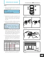
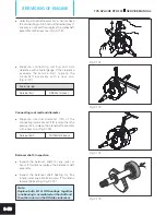
If required, separate the gear complete starter
clutch and remove the one way clutch from
rotor assembly by removing the hexagonal
socket head cap screw (M6x16 - 3 nos.) along
with punched washers. (Fig. 3.132)
5 mm allen key
Tightening torque
12 ± 1 Nm
Note:
Do not separate the gear complete starter
clutch from one way clutch until it is
necessary, to avoid falling of rollers from
one way clutch. Always keep them in
assembled condition.
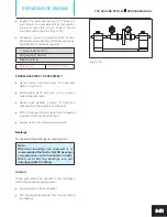
l
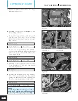
Take out the cam chain (A) and woodruff key
(B) from the crankshaft complete. (Fig. 3.133)
Nose plier
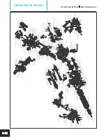
l
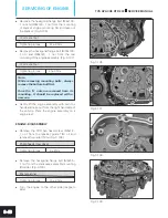
Remove the hexagonal flange bolt (A) (M8x25 -
2 nos.) along with spring washer from LH side
top and bottom mounting of crash guard.
(Fig. 3.134)
l
Remove the hexagonal flange bolt (B) (M8x25 -
1 no.) along with spring washer from RH side
top mounting of crash guard and dislocate the
cable guide (C). (Fig. 3.134)
l
Remove the hexagonal flange bolt (D) (M8x25 -
1 no.) along with spring washer from RH side
bottom mounting of crash guard and take out
the crash guard. (Fig. 3.134)
12 mm spanner
Tightening torque
27 ± 3 Nm
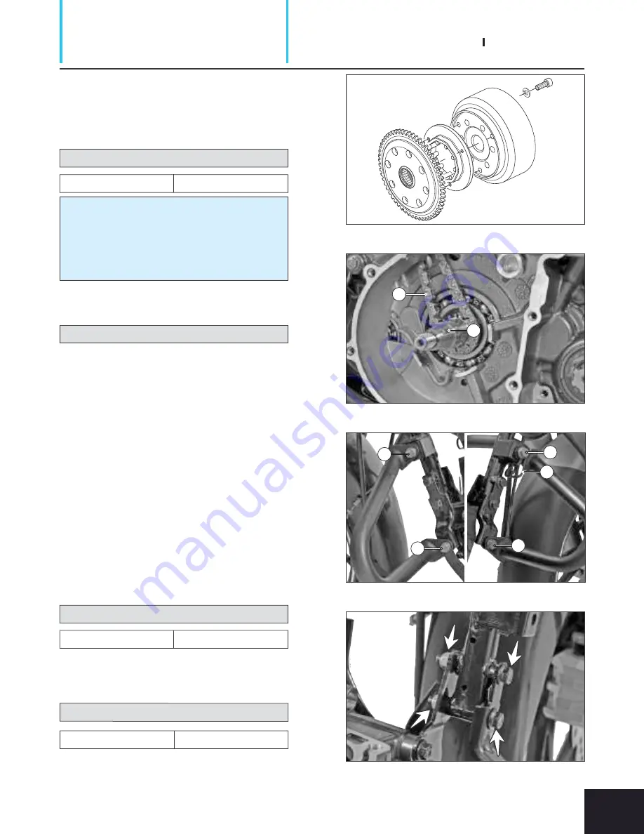
l
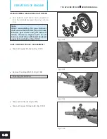
Remove the hexagonal flange bolt (M8x55 -
2 nos.) from the mounting of bracket crash
guard RH and take out the bracket. (Fig. 3.135)
12 mm spanner
Tightening torque 2
7 ± 3 Nm
Fig. 3.132
Fig. 3.134
Fig. 3.133
Fig. 3.135
TVS APACHE RTR 200
SERVICE MANUAL
SERVICING OF ENGINE
3-39
A
A
B
D
C
A
B


