l
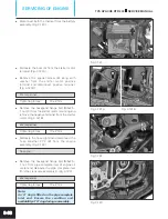
Take out thrust washer from the drive shaft
assembly gear 2nd driven seating area.
(Fig. 3.152)
l
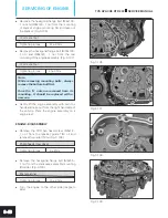
Pull out crankshaft assembly from the
crankcase assembly LH by gently tapping it
from the other side. (Fig. 3.153)
Note:
While removing the crankshaft assembly,
ensure that the balancer shaft is rotated to
the other side and not obstructing the
crankshaft.
l
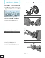
Take out the balancer shaft complete as an
assembly. (Fig. 3.154)
l
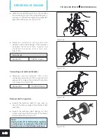
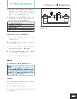
Remove hexagonal bolt (M6x16 - 1 no.) from
the bracket idler gear mounting and dislocate
the bracket idle gear. (Fig. 3.155)
8 mm spanner
Tightening torque
10 ± 2 Nm
Fig. 3.152
Fig. 3.153
TVS APACHE RTR 200
SERVICE MANUAL
SERVICING OF ENGINE
3-44
Fig. 3.154
Fig. 3.155


