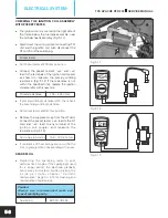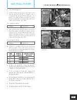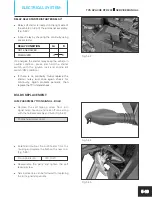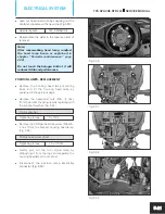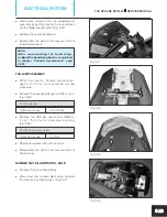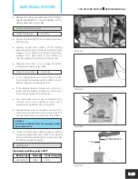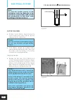
Fig. 5.23
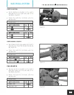
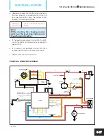
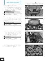
Fig. 5.24
TVS APACHE RTR 200
SERVICE MANUAL
ELECTRICAL SYSTEM
5-11
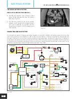
A negative input from the common earth junction is directly connected to the position lamps. On switching ‘ON’ the
ignition lock the lamps glows directly. Similarly, the smart phone charger also gets the negative input from the
common earth junction and it will be ready for charging the smart phones.
When the brake lamp switch front or rear is operated (brake applied), the DC current from either of the switch is
supplied to the brake lamp. A negative earth connection from the common earth junction is connected to the lamp
and hence the lamp glows. Similarly, when the horn button is pressed, the negative input from the common junction
is connected to the horns. Since the horns are connected to the ignition lock’s DC output directly, on pressing the
switch the horns blows.
A DC output from the ignition lock is connected to the speedometer assembly for its operation. A input signal from
the gear position sensor is connected to the speedometer and the TCI unit for gear position sensing. A neutral
indication signal is connected to the TCI unit from the speedometer for electric start operation. The fuel level
indicator in the speedometer gets an input signal in the from of variable resistance from the fuel sender unit. Based
on these signals the fuel level indicator shows the fuel level indication.
An input voltage and a negative supply are given to the speed sensor from the speedometer. The output signal from
the speed sensor is connected to the speedometer. Based on these signals the speed indication is shown.
Speedometer shows engine rpm based on the engine speed signal received from the TCI unit.
A DC output from the ignition lock is connected to the electronic flasher unit. The output from the flasher unit is
connected to the switch turn signal. When the switch is slid to the ‘right’ or ‘left’ the respective front and rear turn
signal lamps glows along with the turn signal indicator on the speedometer .
HORNS (12V DC)
l
The horns are mounted on the frame at the
front side of the vehicle below the fuel tank.
(Fig. 5.23)
l
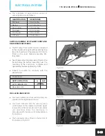
The DC output orange wire (Or) from the
ignition lock is connected to the horns directly
and the negative green wire (G) from the horns
is connected to earth through the horn switch.
l
The horn switch is located on the switch
assembly handle LH. (Fig. 5.24)
l
Check the switch for continuity with the
pocket tester.
Pocket tester
SWITCH POSITION
G
BW
PRESS - ON
O
O
RELEASE - OFF


