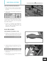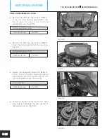
l
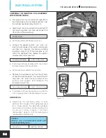
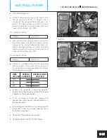
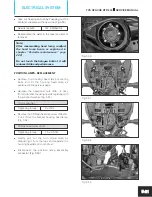
Gradually increase the throttle while observing
the rpm indicator of speedometer. Once the
rpm reaches 4000, check the pocket tester
reading. The reading should be
Charging
14.5 ± 0.3V at 2500 rpm and
performance
above
Note:
While checking the charging current,
switch on the head lamp high beam to
know the correct reading.
l
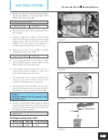
If the reading measured is not within the limit,
check the stator coil resistance as explained in
page no. 5-5 .
l
If the stator coil resistance found OK, then
replace the RR unit with a new and re-check.
l
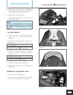
Reassemble the cover frame RH.
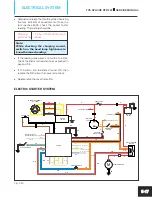
ELECTRIC STARTER SYSTEM
5-17
TVS APACHE RTR 200
SERVICE MANUAL
ELECTRICAL SYSTEM
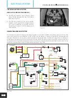
Fig. 5.40
RELAY STARTER
MOTOR
STARTER SWITCH
R
R
STARTER MOTOR
M
BW
GrR
GrR
OrB
PULSAR COIL
Y
Y
Y
RR UNIT
12V, DC
BATTERY
12V, 9Ah
R
R
BW
R
R
R
W
W
Br
FUSE 15A (DC)
FUSE 10A
(HEAD LAMP)
TO OTHER CIRCUITS
TO IGNITION COIL
ENGINE KILL
SWITCH
Or
Or
Or
OrB
OrB
OrB
IGNITION
LOCK
R
RB
OFF
ON
W
Br
TO SPEEDOMETER
MAGNETO ASSEMBLY
12V - 200W
Y
Y
Y
BW
BW
BIR
WB
FOR HEAD LAMP OPERATION
FROM SPEEDOMETER
FOR NEUTRAL POSITION
FROM GEAR POSITION
SENSOR
YB
TO SPEEDOMETER
(FOR TACHO
INDICATION)
FROM
THERMAL SENSOR
TO IGNITION COIL
TCI UNIT
RW
RY
BBr
YOr
Ybl
WR
YB
OrB
Bl
BIB
BIB
BIB
GR
GrR
GrR
GrR
OrB
OrB
P
WG
BW
CLUTCH SWITCH


