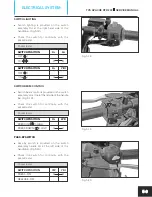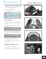
Fig. 5.57
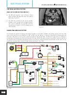
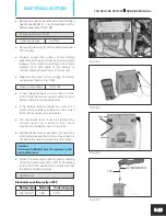
Fig. 5.58
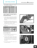
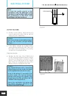
Fig. 5.59
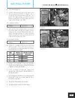
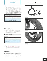
Fig. 5.60
l
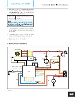
Disconnect coupler from the speedometer
assembly by gently pressing the lock and take
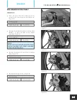
out the digital speedometer. (Fig. 5.57)
l
Replace the new speedometer.
l
Reassemble the parts in the reverse order of
removal procedure.
Note:
After reassembling the head lamp,
readjust the head lamp bea
m as explained
in chapter “Periodic maintenance” page
2-38).
TAIL LAMP ASSEMBLY
l
Refer the chapter “Periodic maintenance”
page 2-10 for tail cover assembly rem
oval
procedure.
l
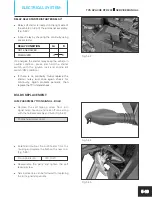
Remove the hexagonal flange nut (M6 - 2 nos.).
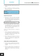
(Fig. 5.58)
10 mm spanner
Tightening torque
2.5 ± 0.5 Nm
l
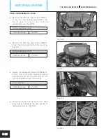
Remove the CRR pan head screw (M6x16 -
2 nos.) from the tail assembly mounting.
(Fig. 5.59)
Phillips head screw driver
Tightening torque
3 ± 1 Nm
l
Replace lamp assembly with new one.
l
Reassemble the parts in the reverse order of
dismantling.
NUMBER PLATE ILLUMINATOR - BULB
l
Remove the rear seat assembly.
l
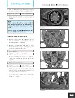
Disconnect the number plate lamp couplers
from the main wiring harness. (Fig. 5.60)
TVS APACHE RTR 200
SERVICE MANUAL
ELECTRICAL SYSTEM
5-23

