background image

TVS APACHE RTR 200

SERVICE MANUAL

PERIODIC MAINTENANCE

2-45

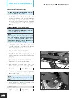
BALL JOINT GEAR SHIFT LEVER

Lubricate every 6000 km using grease

l


Lubricate  the  ball  joint  gear  shift  lever  using 

grease  every  6000  km  for  easy  operation  of 
lever and smooth gear shifting. (Fig. 2.121)

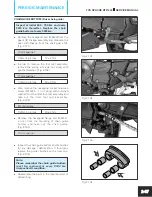
CENTER AND SIDE STAND PIVOT

Lubricate at initial 500 - 750 km and every      
3000 km thereafter.

l

  Lubricate the pivots of center stand and side 

stand  using  TRU4  oil  for  smooth  operation. 
(Fig. 2.122)

SWING ARM BEARINGS

Lubricate using grease every two years.

l

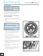
Loosen hexagonal screw (M6x20 - 1 no) from  
the  arm  gear  shifter  lever  mounting  and  
dislocate  the  gear  shift  lever  from  the  shaft  
assembly gear shift. (Fig. 2.123)

10 mm spanner


Tightening torque 

10 ± 2 Nm

l

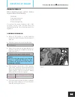
Remove  the  swing  arm  axle  ‘U’  nut  (M12) 
along with punched washer. Fig. 2.124)

 (

17 mm spanner


Tightening torque 

50 ± 5 Nm

l

Also, remove the hexagonal socket head cap   
screw  (M10x25  -  1  no.)  along  with  punched 
washer from the rider foot rest assembly LH 
and  take  out  the  foot  rest  assembly.             
(Fig. 2.124)

8 mm allen key


Tightening torque 

18 ± 2 Nm

Fig. 2.121

Fig. 2.122

Fig. 2.123

Fig. 2.124

Summary of Contents for Apache RTR 200 4V

Page 1: ...SER MAN TVS APACHE RTR 200 4V REVISION 0 SERVICE MANUAL ...

Page 2: ...printing All the illustrations given in this manual may vary from the actual vehicles TVS MOTOR COMPANY LIMITED reserves the right to make changes at any time without prior notice and without incurring any obligation whatsoever No part of this publication should be reproduced without written permission from TVS MOTOR COMPANY LIMITED ...

Page 3: ...ation available during the preparation of manual Modifications or any improvements on product will be communicated through SERVICE INFORMATION BULLETINS from time to time This manual will help to the technicians who already have technical knowledge about motorcycles While servicing certain parts may require replacement For ordering spares please refer Parts catalogue of TVS APACHE RTR 200 4V motor...

Page 4: ...ns on left side and the illustrations on the right side Some of the exploded views occupy full pages In between the running instructions we have used the notations as per the examples given below Note Inspect and set the idling speed after completing all other maintenance actions HOW TO READ THIS MANUAL Heading CHAIN ASSEMBLY DRIVE Sub heading Chain slackness Note This provides further clarificati...

Page 5: ...RIODIC MAINTENANCE 3 Page 3 1 to 3 58 SERVICING OF ENGINE 4 Page 4 1 to 4 19 FUEL LUBRICATION AND EXHAUST SYSTEM 5 Page 5 1 to 5 28 ELECTRICAL SYSTEM 6 Page 6 1 to 6 51 CHASSIS 7 Page 7 1 to 7 15 SERVICE INFORMATION TVS APACHE RTR 200 SERVICE MANUAL GROUP INDEX ...

Page 6: ......

Page 7: ...DE FOR THE PRODUCTION MONTH 3 TECHNICAL SPECIFICATIONS 4 DIMENSIONS AND WEIGHT 4 ENGINE 4 TRANSMISSION 4 GEAR RATIO 5 CHASSIS 5 ELECTRICAL 5 CAPACITIES 6 ADVANTAGES AND SPECIAL FEATURES OF TVS APACHE RTR 200 4V 7 WARRANTY TERMS 7 RUNNING IN PERIOD 7 FUEL AND OIL RECOMMENDATIONS 8 PRECAUTIONS AND GENERAL INSTRUCTIONS 8 LIST OF HAND TOOLS REQUIRED 9 LIST OF SPECIAL TOOLS REQUIRED 9 SPECIAL TOOLS AND...

Page 8: ......

Page 9: ...TVS APACHE RTR 200 4V RIGHT SIDE LEFT SIDE Fig 1 1 Fig 1 2 TVS APACHE RTR 200 SERVICE MANUAL GENERAL INFORMATION 1 1 ...

Page 10: ... identifier Month code Filler Check digit VEHICLE IDENTIFICATION NUMBERS LOCATIONS FRAME NUMBER l The frame serial number is stamped on the right side of the steering head tube Fig 1 3 ENGINE NUMBER l The engine serial number is stamped on the left side crankcase assembly near cylinder block Fig 1 4 6 3 7 Frame type Vehicle type M D World manufacturer identifier Fig 1 3 Fig 1 4 GENERAL INFORMATION...

Page 11: ...0 M 2021 N 2022 P 2023 R 2024 S 2025 T 2026 V 2027 W 2028 X 2029 Y 2030 A JANUARY B FEBRUARY C MARCH D APRIL E MAY F JUNE G JULY H AUGUST K SEPTEMBER L OCTOBER N NOVEMBER P DECEMBER CODE FOR THE PRODUCTION YEAR CODE CODE YEAR CODE FOR THE PRODUCTION MONTH MONTH YEAR AND MONTH CODES GENERAL INFORMATION TVS APACHE RTR 200 SERVICE MANUAL 1 3 ...

Page 12: ...es 4 Carburettor type Keihin CV 30 VE Air filter Viscous Paper filter Oil filter Wire mesh and micronic paper filter Lubrication system Forced wet sump Maximum power in kW 15 09 kW 20 5 PS 8500 rpm Maximum torque in Nm 18 1 Nm 7000 rpm Maximum speed Around 128 km h Engine idling rpm under warm condition 1500 100 rpm Starting system Electric starter TRANSMISSION Clutch Wet multiplate type Gear shif...

Page 13: ... 2 Tyre pressure Front 1 75 kg cm 25 PSI 2 Rear Solo 2 00 kg cm 28 PSI 2 Dual 2 25 kg cm 32 PSI ELECTRICAL Type AC generator Ignition system IDI Engine load based digital ignition Spark plug BOSCH UR4KE Battery type 12V 9 Ah Body earthing Negative terminal Generator Fly wheel magneto 12V 200W Head lamp 12V 60 55W H4 x 1 Position lamp LED lamp 2W x 2 Tail brake lamp LED indicator 1W max 2 5W max Tu...

Page 14: ...ACITIES Fuel type Unleaded petrol Fuel tank capacity 12 litres including reserve Reserve 2 5 litres Engine cum transmission oil grade TVS TRU4 FULLY SYNTHETIC oil SAE 10W30 API SL JASO MA2 Engine cum transmission oil capacity 1200 ml after draining 1400 ml incase of disassembly Front fork oil grade KYB G10 oil Front fork oil quantity 325 2 cc Brake fluid TVS Griling DOT 3 DOT 4 GENERAL INFORMATION...

Page 15: ...racing l Roto petal disc brakes l Race grip Remora tyres Pirelli tyres optional l Aluminium forged handle bars l Interactive racing display l All new Day LED lamp l Aggressive tank cowl l Racing ergo split seat assembly l Longer wheel base for better stability WARRANTY TERMS TVS APACHE RTR 200 4V 24 months from the date of sale or 30 000 km whichever of the two occurs earlier RUNNING IN PERIOD The...

Page 16: ...toplex 2 Chain lubricant TVS Motor Company TRU SPRAY PRECAUTIONS AND GENERAL INSTRUCTIONS Observe the following precautions without fail when dismantling and reassembling l Do not run the engine indoors with little or no ventilation l Be sure to replace gaskets O rings circlips and cotter pins with new ones for safety l When tightening nuts and bolts start first with the larger or centre ones Tigh...

Page 17: ...rsal oil seal remover LIST OF SPECIAL TOOLS REQUIRED 1 Flat head spanners 7 mm 8 mm 10 mm 12 mm 14 mm and 21 mm 2 Ring spanners 8 mm 9 mm 10 mm 11 mm 12 mm 13 mm 14 mm 16 mm 17 mm 22 mm 24 mm 27 mm and 32 mm 3 Tubular spanners 8 mm 10 mm 12 mm 14 mm 16 mm and 17 mm 4 Socket spanners 12 mm 14 mm 17 mm 22 mm 27 mm and 32 mm 5 Allen keys 4 mm 6 mm 8 mm 10 mm and 12 mm 6 Screw drivers Flat screw drive...

Page 18: ...e valve tappet clearance Fig 1 6B 3 Puller assembly crankcase M131 011 0 Fig 1 7A l Used to separate the LH and RH side crankcases Fig 1 7B 4 Clutch holder tool N231 001 0 Fig 1 8A l Used to hold the clutch assembly during clutch assembly mounting nut removal Fig 1 8B Fig 1 5B Fig 1 5A Fig 1 6B Fig 1 7B Fig 1 6A Fig 1 7A 1 10 GENERAL INFORMATION TVS APACHE RTR 200 SERVICE MANUAL Fig 1 8B Fig 1 8A ...

Page 19: ... oil seal and dust cap Fig 1 10B 7 Tool fork cylinder holder N931 011 0 Fig 1 11A l Used to hold the front fork cylinder during fork leg assembly dismantling Fig 1 11B 8 Tool pre load adjuster N931 012 0 Fig 1 12A l Used to adjust the rear mono shock spring pre load Fig 1 12B GENERAL INFORMATION TVS APACHE RTR 200 SERVICE MANUAL 1 11 Fig 1 9B Fig 1 10B Fig 1 11B Fig 1 12B Fig 1 9A Fig 1 10A Fig 1 ...

Page 20: ...4 0 Fig 1 14A l Used to remove assemble the steering lock nut and arrester steering stem Fig 1 14B 11 Tool swing arm service N931 015 0 Fig 1 15A l Used to remove and reassemble the swing arm needle bearings Fig 1 15B 12 Tool steering cup remover N931 016 0 Fig 1 16A l Used to remove the top and bottom steering cups Fig 1 16B GENERAL INFORMATION TVS APACHE RTR 200 SERVICE MANUAL 1 12 Fig 1 13B Fig...

Page 21: ...e steering inner during servicing of steering Fig 1 18B 15 Extractor inlet and exhaust valve S131 002 0 Fig 1 19A l Used to hold the compress the inlet and exhaust value spring during removal of valves Fig 1 19B 16 Bearing installer set S131 050 0 Fig 1 20A l Used to remove assemble the bearings oil seals and bushes Fig 1 20B GENERAL INFORMATION TVS APACHE RTR 200 SERVICE MANUAL 1 13 Fig 1 17B Fig...

Page 22: ...ain bearing from the crankshaft Fig 1 21B 18 Front fork oil level gauge 031 180 0 Fig 1 22A l Used to maintain the front fork oil level at the specified height Fig 1 22B 19 Universal oil seal remover 031 240 1 Fig 1 23A l Used to remove the installed oil seals Fig 1 23B Fig 1 23B Fig 1 22B Fig 1 23A Fig 1 22A Fig 1 21B Fig 1 21A ...

Page 23: ... PLATES 24 ENGINE BREATHER HOSE 24 CARBURETTOR RUBBER DUCTS 24 FUEL COCK SEDIMENT BOWL 25 HOSE FUEL 25 CABLE ASSEMBLY CLUTCH 25 CABLE ASSEMBLY THROTTLE 26 THROTTLE GRIP 27 CHOCK OPERATION 28 STEERING PLAY AND FREENESS 28 FRONT FORK OIL 31 FRONT AND REAR SUSPENSION 31 ALL FASTENERS 32 DRIVE CHAIN 32 RETAINER OIL SEAL 36 CHAIN GUIDE BOTTOM 37 ALL BULBS HORN AND SWITCHES 38 HEAD LAMP BEAM 38 BATTERY ...

Page 24: ......

Page 25: ...8000 km Front and rear suspension I I I I I I 3 All fasteners I TI I TI I TI I TI I TI I TI Tighten if necessary Drive chain C L A C L A C L A C L A C L A C L A Adjust if necessary PERIODIC MAINTENANCE For a trouble free performance of the vehicle and its longer life the vehicle should be periodically inspected for wear of components carbon deposits stretched cables etc The worn out components to ...

Page 26: ...y three years Master cylinder cups Replace every 21000 km Wheel freeness I I I I I I Tyre pressure at cold condition I S I S I S I S I S I S Engine idling RPM I S I S I S I S I S I S 7 Idling CO I S I S every 12000 km Ball joint gear shift lever L L L Lubricate using grease Centre side stand pivot L L L L L L Lubricate using TRU4 oil Swing arm bearings C L with fresh Bechem premium grade 3 grease ...

Page 27: ...ing it from the seat release cable B Fig 2 2 l To reassemble the utility box reverse the removal procedure Front seat rider seat removal l To remove the front seat 2 remove the rear seat refer Fig 2 1 and take out the key from the lock l Pull the seat release cable A to release seat lock Keeping the seat release cable pulled lift the seat from rear end and slide it backward to remove Fig 2 3 l To ...

Page 28: ...screw driver l Take out the cover frame L by carefully dislocating it from the lugs l To reassemble the cover frame R L locate the lugs of the cover frame at the holes provided on the frame and install the CRR pan head screw M6x16 3 nos each side Phillips head screw driver Tightening torque 3 1 Nm Caution Make sure that the cover frame is locked securely in position after installation Note Ensure ...

Page 29: ...efully lift the rear portion of fuel tank and disconnect the fuel sender unit wiring socket Fig 2 8 l Take out the cushion fuel tank rear lower 2 nos from the fuel tank mounting l Remove fuel tank complete along with drain hose by sliding it out from both the cushion fuel tank front Note While reassembling fuel tank complete ensure that fuel sender unit wiring socket is connected and fuel tank dra...

Page 30: ...R pan head screw M6x12 1 no from the mounting of cover fuel tank inner L with the fuel tank Fig 2 10 Phillips head screw driver Tightening torque 10 2 Nm l Remove the CRR pan head screw M6x12 2 nos from the cover fuel tank front mounting Fig 2 11A l Similarly remove the CRR pan head screw M6x12 1 no from the cover fuel tank rear mounting Fig 2 11B Phillips head screw driver Tightening torque 10 2 ...

Page 31: ...RR pan head screw M5x12 from the fuel tank cap inner mounting Fig 2 15 Phillips head screw driver Tightening torque 4 5 0 5 Nm l Take out the fuel tank cap assembly along with seal fuel tank cap Note Ensure the presence of seal in the fuel cap assembly before re installing the cap l Carefully dislocate and remove the cover fuel tank assembly from the fuel tank l Remove the CRR flanged pan head tap...

Page 32: ... tank top l Remove the CRR flanged pan head tap screw ST4 2x13 4 nos from the mounting of cover fuel tank outer L Fig 2 18 Phillips head screw driver Tightening torque 1 0 5 Nm l Carefully dislocate the cover fuel tank outer L from the cover fuel tank top l Remove the CRR flanged pan head tap screw ST4 2x13 2 nos from the mounting of grill cover fuel tank R Fig 2 19 Phillips head screw driver Tigh...

Page 33: ...assembly into the fuel tank Ensure the availability of cushions at the respective places Else it may create rattling noise Fig 2 20 TVS APACHE RTR 200 SERVICE MANUAL PERIODIC MAINTENANCE 2 9 CAP FUEL TANK SEAL CAP INLET FUEL TANK COMPLETE O RING FUEL TANK COMPLETE COVER FUEL TANK OUTER L COVER FUEL TANK OUTER R COVER FUEL TANK INNER L COVER FUEL TANK INNER R GRILL COVER FUEL TANK L GRILL COVER FUE...

Page 34: ...ect the rear seat lock cable B from the seat latch and release it from its locating bracket Fig 2 22 l Similarly release the seat release cable C of front seat from its locating bracket Fig 2 22 l Remove hexagonal bolt M6x20 4 nos along with punched washers from the mounting the tail cover assembly with the chassis Fig 2 23 10 mm spanner Tightening torque 6 2 Nm l Remove hexagonal bolt M6x20 1 no ...

Page 35: ...ove the CRR pan head screw M6x16 4 nos from the mounting of tail cover assembly bottom Fig 2 26 Phillips head screw driver Tightening torque 3 1 Nm l Gently dislocate and take out the tail cover assembly from the vehicle l Reassemble the parts in the reverse order of removal Note Ensure the availability of cushions at the top mounting of tail cover assembly TVS APACHE RTR 200 SERVICE MANUAL PERIOD...

Page 36: ...ating temperature and switch OFF l Remove the gauge oil level to facilitate easy draining of oil Fig 2 27 l Loosen and remove the hexagonal flange head bolts M6x20 3 nos Fig 2 28 8mm spanner Tightening torque 10 2 Nm l Remove the cap oil strainer along with O ring and drain the engine cum transmission oil Oil filter Strainer l Loosen the CRR pan head screw M5x12 2 nos and remove the strainer compl...

Page 37: ...mum levels Fig 2 30 l If the oil level is below the minimum level top up with the TVS TRU4 FULLY SYNTHETIC oil SAE 10W30 API SL JASO MA2 upto the maximum level Note Check the condition of the O ring A and replace if required Ensure the availability of O ring in the gauge during reassembly FILTER COMPLETE ENGINE OIL Replace at initial 500 750 km and every 6000 km there after l Before removing the f...

Page 38: ...e type of the spark plug Inspect and clean at initial 500 750 km Replace spark plug every 12000 km l Neglecting the spark plug leads to difficulty in starting and poor performance l Before removing the spark plug clean the spark plug surroundings to prevent any foreign materials from falling inside the cylinder bore l Disconnect the sparkplug cap and remove the spark plug Fig 2 34 Plug spanner l C...

Page 39: ...recommended make and type of spark plug for the good performance of the engine Do not use spark plug that fallen from the hand carton box internally they may have crack and the profile may change Sparkplug BOSCH UR4KE l Visually inspect the spark plug gap If the gap is found more replace the plug with a new Spark plug gap 0 7 mm Caution Since hook profile spark plug is used do not try to adjust th...

Page 40: ...ht sized spark plug spanner Tightening torque 10 15 Nm AIR CLEANER ELEMENT Replace cleaner element every 12000 km Note Replace the air cleaner element filter holder complete early if it is clogged with excessive dirt based on the usage and environment or found with any damage Cleaning the air cleaner element with solvent other chemicals can damage the element and consequently reduces the life of e...

Page 41: ...cement However the air cleaner element must be replaced at every 12000 km Note While removing reassembling the air cleaner element do not hold the paper element portion Hold only at the sides l Inspect and ensure that the cover air cleaner and case air cleaner assembly is clear from any dust dirt and foreign particles Fig 2 43 l Before reassembling the air cleaner element clean the case air cleane...

Page 42: ...g rpm at initial 500 750 km and every 3000 km there after Inspect and set idling CO at initial 500 750 km and every 12000 km there after l If the engine performance is good the mixture volume control screw A MCS screw need not to be disturb The idling speed can be adjust only with idling screw B to specified limit Fig 2 44 Idling rpm 1500 100 rpm Note Inspect and set the idling speed after attendi...

Page 43: ... to measure the engine rpm Tachometer l Turn the idling screw so that the engine idles at the specified idling rpm 1400 100 rpm Fig 2 46 l After adjusting the idling rpm check the CO If necessary readjust the mixture control screw to set the CO to the specified limit refer page no 4 17 for CO setting procedure Idling CO 1 0 to 3 0 with SAI CAT TAPPET CLEARANCE Inspect and adjust at initial 500 750...

Page 44: ...as shown in the figure l Remove plug TDC A along with the gasket Fig 2 50 17 mm spanner Tightening torque 27 5 2 5 Nm l Fig 2 50 Remove plug crankshaft hole B 10 mm allen key Tightening torque 10 2 Nm l Align the TDC mark A on rotor assembly with centre of the inspection hole provided in the cover magneto by rotating the rotor assembly Fig 2 51 17 mm tubular spanner Note At this point both the roc...

Page 45: ...eler gauge l After adjusting to the specified clearance tighten the nut tappet adjusting while holding the screw tappet adjusting in the same position using special tool Fig 2 54 M13 100 70 Tool tappet adjuster Feeler gauge l Reassemble the parts in the reverse order of removal ENGINE OIL COOLER ASSEMBLY Removal l Remove the hexagonal flange bolt M6x20 1 no mounting the pipe complete outlet with t...

Page 46: ... km thereafter l Gently dislocate the guard oil cooler along with cup washers from the oil cooler assembly Fig 2 58 l Visually inspect the oil cooler fins for any blockage l If found any clean them using a small blend tool and compressed air Caution Care should be taken not to damage the fins while cleaning with the tool and compressed air l Inspect the oil cooler fins A for any deformation If it ...

Page 47: ... Refer exploded view for details Fig 2 61 Note Ensure to assemble the O rings at both inlet and outlet pipes ends Ensure the availability of grommet and cup washers at the mounting area of oil cooler assembly TVS APACHE RTR 200 SERVICE MANUAL PERIODIC MAINTENANCE 2 23 OIL COOLER ASSEMBLY HEXAGONAL FLANGE BOLT M6x20 2 Nos HEXAGONAL FLANGE BOLT M6x16 4 Nos GUARD OIL COOLER PIPE COMPLETE INLET O RING...

Page 48: ...vice Replace every 21000 km if required l Visually inspect the engine breather hose for any crack leakage damage or deformation If found any replace the engine breather hose Fig 2 63 CARBURETTOR RUBBER DUCTS Pipe intake complete and Tube outlet Inspect at every 3000 km Replace every 21000 km if required l Visually inspect the pipe intake complete and air cleaner tube outlet for any crack leakage d...

Page 49: ...e threads of sediment bowl while reassembling as it may lead to fuel leak HOSE FUEL Inspect hose fuel at initial 500 750 km and every 3000 km thereafter Replace every three years l Inspect the hose fuel and connections for damage and leakage Fig 2 67 l If any abnormality is found replace the hose fuel However fuel hose must be replaced every three years CABLE ASSEMBLY CLUTCH FREE PLAY Inspect adju...

Page 50: ... FREE PLAY Inspect adjust and lubricate ends with grease at initial 500 750 km and every 3000 km there after l For checking the cable assembly throttle throttle cable free play first dislocate the boot throttle A from its position Fig 2 70 l Gently pull the throttle cable while holding the adjuster A to check the free play Fig 2 71 If the free play is more or less adjust as follow Free play 1 2 mm...

Page 51: ...is obtained And then tighten the lock nut A while holding the cable adjuster C Fig 2 72 10 mm spanner THROTTLE GRIP Lubricate with grease every 6000 km l Inspect throttle grip for smooth rotation If found hard remove and lubricate as explained below l Remove the throttle cable locking screw from throttle case lower Fig 2 73 Phillips head screw driver Tightening torque 2 25 0 25 Nm l Remove the CRR...

Page 52: ... lever at the carburettor for any stuck up Incase found any remove and clean the choke assembly as explained in chapter Fuel lubrication and exhaust system page no 4 3 STEERING PLAY AND FREENESS Inspect at initial 500 750 km Adjust if necessary Clean and lubricate the steering with Bechem premium grade 3 grease every 12000 km l Steering should be adjust correctly for smooth movement of handle bar ...

Page 53: ...k nut A and remove the lock nut steering along with a special washer Fig 2 79 32 mm spanner Tightening torque 80 20 Nm l Loosen hexagonal socket head cap screws A M8x30 2 nos from the mounting of handle bar assembly with the front fork Fig 2 80 6 mm allen key Tightening torque 16 2 Nm l Similarly loosen hexagonal socket head cap screws B M8x45 2 nos from the mounting of lower bracket complete fork...

Page 54: ...o reduce or to increase steering play respectively Fig 2 83 N931 014 0 Tool steering nut 32 mm spanner l After ensuring there is no play in the steering assemble the lock washer and arrester steering stem top l Locate the lock washer properly and tighten the steering stem top Finally lock the lock washer and then assemble the other parts in the reverse order of removal l Finally tighten the steeri...

Page 55: ...emblies need to be serviced l However the front fork oil need to be replaced every 18000 km Refer chapter Chassis page no 6 17 for service and oil replacement procedure of front fork FRONT AND REAR SUSPENSION Inspect for proper function at initial 500 750 km and every 3000 km thereafter l Inspect the front fork both the legs for smooth operation proper action If found any abnormality service the l...

Page 56: ...cle running l If dirt dust particles deposition on the drive chain is found less the drive chain can be cleaned and lubricated on the vehicle itself l Place the vehicle on the center stand l Clean the drive chain thoroughly using a cloth wet with kerosene while rotating the wheel assembly l Allow 3 minutes for the drive chain surface to dry and wipe the surface with dry cloth l After cleaning the ...

Page 57: ...ate the chain while rotating the wheel slowly Fig 2 89 Note Shake TRU SPRAY container well before use Attach the extension tube to the TRU SPRAY container for pin point application Hold the container upright and spray from a distance of 4 6 inches as shown in the figure l If dirt dust particles deposition on the drive chain is found more it is recommended for the first time alone to follow the pro...

Page 58: ...along with punched washer Fig 2 93 17 mm spanner Tightening torque 40 4 Nm l Also remove the hexagonal socket head cap screw M10x25 1 no along with punched washer from the rider foot rest assembly and take out the rider foot rest assembly Fig 2 93 8 mm allen key Tightening torque 18 2 Nm l Remove the hexagonal bolts 2 nos and take out the lock washer by rotating it either clockwise or anti clockwi...

Page 59: ... 2 nos along with the washers from the chain guard Fig 2 97 10 mm spanner Tightening torque 8 2 Nm l Push the rear wheel from the back towards front so that the drive chain loosens and hangs as shown Fig 2 98 l Now lift the chain guard upward Gently take out the drive chain by dislocating it from the rear sprocket and swing arm assembly l Clean the drive chain by dipping it in kerosene Brush off a...

Page 60: ...ate RETAINER OIL SEAL Drive shaft oil seal Inspect at initial 500 750 km and every 3000 km thereafter Replace the retainer every 9000 km l Remove the sprocket engine along with drive chain as explained in page no 2 33 Inspect the retainer oil seal for any physical damage If found any l Remove the hexagonal flange bolt M6x16 2 nos from the mounting of retainer oil seal and take out Fig 2 100 8 mm s...

Page 61: ...tening torque 50 5 Nm l Also remove the hexagonal socket head cap screw M10x25 1 no along with punched washer from the rider foot rest assembly and take out the rider foot rest assembly Fig 2 102 8 mm allen key Tightening torque 18 2 Nm l Remove the hexagonal flange bolt M6x16 2 nos from the mounting of chain guide bottom and take out the chain guide Fig 2 103 10 mm spanner l Inspect the chain gui...

Page 62: ...cedure HEAD LAMP BEAM ADJUSTMENT Inspect and adjust at initial 500 750 km and every 3000 km there after l Keeping the bike in a straight line sit on the bike to aim the head lamp beam vertically Focus head lamp high beam on a vertical screen which is at a distance of 10 meter from the head lamp bulb s center point Adjust head lamp assembly such that the focal point of high beam on the screen is 10...

Page 63: ...ge no 5 24 Note While removing the battery terminals remove the ve terminal first While reconnecting connect the ve terminal at last l Visually inspect the surface of the battery container If any sign of cracking or electrolyte leakage from the sides of battery is noticed replace the battery with a new l Measure the open circuit voltage of battery using pocket tester Fig 2 107 Pocket tester Open c...

Page 64: ...val and reconnect the terminals Apply petroleum gelly in the terminals to avoid corrosion BRAKES Inspect the front brake and rear brake effectiveness at initial 500 750 km and every 3000 km thereafter Inspect front and rear brake fluid level and top up at initial 500 750 km and every 3000 km thereafter Replace brake fluid every 21000 km Inspect front and rear brake pad wear at initial 500 750 km a...

Page 65: ...ecommended grade Brake fluid TVS Griling DOT3 DOT4 l Reassemble the parts and apply the front brake to check the effectiveness l If the lever travel is more or the lever feels soft or spongy air bleeding from the system to be carried out Refer chapter Chassis page no 6 7 for bleeding procedure Brake fluid level Rear brake l Remove cover frame R refer page 2 4 for removal procedure Place the vehicl...

Page 66: ...s Fig 2 114 l When the wear exceeds the limit line replace the pad as a set Refer chapter Chassis page no 6 page no 6 36 for the front and rear 5 pads replacement procedure Note Brake pad wear can be checked without removing the caliper assembly from the fork and rear wheel Caution Replace the brake pad with set otherwise braking performance will be adversely affected Front rear brake hoses l Insp...

Page 67: ... wheel rotation increases fuel consumption TYRES Inspect at initial 500 750 km and at every 3000 km thereafter Tyre tread condition l Using the vehicle with excessively worn tyres will decrease riding stability and consequently invite a dangerous situation due to loss of control It is highly recommended to replace the tyre with a new one when the groove depth of tyre from tread surface reaches the...

Page 68: ...essure for good road stability and longer tyre life Inflate tyres in cold condition to the pressure as given below Tyre pressure gauge Tyre pressure Front Rear Kg cm psi Kg cm psi Solo riding 1 75 25 2 00 28 Dual riding 1 75 25 2 25 32 Note Low tyre pressure consumes more fuel IDLING CO Inspect and adjust at initial 500 750 km and every 12000 km thereafter l When the engine performance is generall...

Page 69: ...tion Fig 2 122 SWING ARM BEARINGS Lubricate using grease every two years l Loosen hexagonal screw M6x20 1 no from the arm gear shifter lever mounting and dislocate the gear shift lever from the shaft assembly gear shift Fig 2 123 10 mm spanner Tightening torque 10 2 Nm l Remove the swing arm axle U nut M12 along with punched washer Fig 2 124 17 mm spanner Tightening torque 50 5 Nm l Also remove th...

Page 70: ...unched washer from the rider foot rest assembly RH Fig 2 126 8 mm allen key Tightening torque 18 2 Nm l Remove the CRR pan head screw M6x16 1 no from the rider foot rest assembly RH top mounting Fig 2 127 Phillips head screw driver Tightening torque 10 2 Nm l Draw out shaft complete swing arm by gently tapping at the other side Fig 2 128 Nylon hammer Note Use a suitable guide in place of shaft com...

Page 71: ...moving the guide inserted earlier from the other side Note Insert the swing arm shaft in such a way that the LH side dust seal swing arm and sleeve can be removed easily and the needle bearing can be accessed for lubrication l Now take out the dust seal swinging arm and sleeve swing arm from the LH side of the swing arm assembly Fig 2 130 l Clean the sleeve dust seal and swing arm needle bearing u...

Page 72: ...ion and the wheel is not having any axial movement on the fixture l Rotate the wheel by hand and mark Q at the top as shown in the figure when the wheel stops rotating comes to a halt Fig 2 131 l Rotate the wheel five times l If the Q marked on the wheel stops randomly at different positions on each of the five rotations then the wheel is considered as balanced sufficiently l Else if the Q marked ...

Page 73: ...inal confirmation rotate the wheel further turn by hand and yet again another turn In both the cases if the wheel comes to a rest after turn rotation it may be concluded that the wheel is balanced After final confirmation the balancing weight must be fixed permanently at the locations decided earlier Follow the procedure given below for fixing the weight permanently 1 Remove the temporarily fixed ...

Page 74: ...2117 g mm in rear wheel for balance quality grade G40 as per the method of unbalance measurement specified in ISO 1940 1 2003 Note The sum total of all balancing weights fixed on a single wheel rim shall not exceed 60 g in front wheel and 70 g in rear wheel irrespective of the procedure used for balancing manual or automatic Use genuine TVS M approved Balancing weights only refer Table 1 Removal u...

Page 75: ...operated under wet or rainy conditions Before lubricating each part clean off any rusty spots and wipe off any grease oil dirt or grime 2 51 Fig 2 135 DRIVE CHAIN TRU SPRAY CENTRE STAND AND SIDE STAND PIVOTS TRU4 oil THROTTLE GRIP Grease BRAKE PEDAL SHAFT TRU4 oil STEERING BEARINGS Grease Dotted line indicates RH side lubricating points Lubricate all cable ends using grease SWING ARM BEARINGS BALL...

Page 76: ...rs on the speedometer dial l Press the Mode button A till the display changes to HIGH SPEED mode Fig 2 136 Note Please remember that the service reminder indicator of speedometer can be reset only in HIGH SPEED mode l Now press and hold both Mode and Set buttons A B till the service reminder indicator disappears Fig 2 137 l Turn OFF and turn ON the ignition and once again confirm that the indicato...

Page 77: ...PISTON AND RINGS PISTON SERVICING 24 REMOVAL 24 INSPECTION 26 REASSEMBLY 29 GEAR BOX ASSEMBLY CRANKSHAFT ASSEMBLY AND BALANCER SHAFT ASSEMBLY SERVICING 31 REMOVAL OF ENGINE ASSEMBLY FROM THE VEHICLE 31 ENGINE DISASSEMBLY 40 GEAR ASSEMBLY BALANCER SHAFT DRIVEN 46 SHAFT COMPLETE DRIVE DISASSEMBLY 46 INSPECTION 47 REASSEMBLY 48 ENGINE COMPONENTS INSPECTION 49 ENGINE ASSEMBLY REASSEMBLY 51 CRANKCASE A...

Page 78: ......

Page 79: ...unt the compression gauge adaptor to the plug hole taking care to make the connection leak proof Fig 3 1 Compression gauge and special adopter Caution Before mounting the gauge enure that the gauge is calibrated Similarly after mounting the gauge ensure that there is no leakage in the line l With the fuel cock knob in OFF position switch OFF the ignition open the throttle fully and crank the engin...

Page 80: ...engine mounted on the vehicle itself Normally clutch is serviced for Loss of power low pickup Jerking of vehicle Any abnormal noise from clutch Kick slip l Drain engine cum transmission oil as explained in chapter Periodic maintenance page no 2 12 l After draining always measure the oil quantity using a measuring jar l Remove filter complete engine oil as explained in chapter Periodic maintenance ...

Page 81: ... torque 10 2 Nm l Remove the hexagonal socket head cap screw M6x16 1 no from the cover clutch mounting Fig 3 6 4 mm allen key Tightening torque 10 2 Nm Caution While reassembling ensure to assemble the hexagonal socket head cap screw without fail to avoid leakage of oil l Remove the hexagonal flange bolts M6x35 11 nos from the cover clutch mounting Fig 3 7 8 mm spanner Tightening torque 10 2 Nm l ...

Page 82: ... loading of plate l Take out plate clutch release l Take out the spring clutch 4 nos Fig 3 10 Caution While reassembling ensure all the four clutch springs are having same colour grade l Using special tool hold the disc clutch pressure and remove nut clutch shaft slotted nut Fig 3 11 N231 001 0 Clutch holding tool N231 002 0 Clutch nut tightening tool 27 mm spanner Tightening torque 60 10 Nm Cauti...

Page 83: ...g as shown Care should be taken to reassemble the top drive plate in the same position l Separate the hub clutch plate clutch driven 5 nos plate clutch drive 4 nos and disc clutch pressure Fig 3 14 l Remove thrust washer clutch hub from the shaft complete counter Fig 3 15A l Pull out gear assembly primary driven along with a clip primary driven gear from gear complete kick starter Fig 3 15B Note W...

Page 84: ...f any replace the plates as a set Plate clutch driven l Inspect the distortion of plate clutch driven using a feeler gauge as shown Fig 3 18 l Check every individual plates Hold the plates with three fingers and insert the feeler gauge between the surface plate and driven plate at 3 to 4 locations to determine the distortion If the distortion is more than the service limit change the plate clutch ...

Page 85: ...embly l Before reassembling inspect the bearing clutch release plate for any abnormal noise and smooth rotation Replace bearing with a new one if found defective l Ensure the clutch plates are held firmly together by checking the play between the drive plates after tightening the plate clutch release bolts Fig 3 22 l Before reassembling cover clutch ensure the assembly of a ball and pin clutch rel...

Page 86: ...se clip A of tube air cleaner outlet and hose clip B of pipe intake complete Fig 3 24 Phillips head screw driver l Gently pull out the carburettor assembly along with the control cables and carefully hang it on the frame itself l Remove the plug A using small flat screw driver from the adjuster assembly Fig 3 25A l Using a small flat screw driver lock the adjuster plunger by rotating it in clockwi...

Page 87: ...g of pipe complete SAI at cylinder block Fig 3 28A l Remove the hexagonal bolt M6x16 1no from the mounting of pipe complete SAI at magneto cover and dislocate the pipe complete SAI Fig 3 28B 8 mm spanner Tightening torque 5 5 0 5 Nm l Disconnect the wiring socket A of ignition coil from the wiring harness Fig 3 29 l Remove the hexagonal flange bolt M6x20 2 nos from the mounting of ignition coil as...

Page 88: ...engine guard as an assembly l Remove the hexagonal socket head cap screw M8x30 2 nos from the muffler assembly front mounting Fig 3 32A l Remove the hexagonal socket head cap screw M8x25 1 no from the center mounting of muffler assembly with punched washer Fig 3 32B 6 mm allen key Tightening torque 18 1 1 3 Nm l Remove the hexagonal bolt M8x60 1 no from the muffler assembly rear mounting along wit...

Page 89: ...linder head Fig 3 36 Note While reassembling inspect the condition of the packing seal If any distortion damage is found replace the packing with a new one l Slowly rotate the rear wheel and engage first gear l Now remove the hexagonal flange bolt M8x1 25 LH from the cam shaft assembly Fig 3 37 10 mm spanner Tightening torque 18 2 Nm Caution Since left hand type thread is used in the bolt it shoul...

Page 90: ...ake out the washer camshaft sprocket from the camshaft Fig 3 39 Nose plier l Take out the cam chain tensioner by removing the bolt cam chain tensioner along with washer cam chain tensioner Fig 3 40 12 mm spanner Tightening torque 12 2 Nm l Remove the bolt cylinder head 4 nos from the mounting of cylinder head complete Fig 3 41 12 mm spanner Tightening torque 24 5 2 5 Nm Note While reassembling alw...

Page 91: ... head assembly or from cylinder block Fig 3 44 l Take out the gasket cylinder head B Fig 3 44 Note While reassembling check the gasket for any damage scoring deformation or leakage marks If found replace the gasket with a new one CYLINDER HEAD ASSEMBLY DISASSEMBLY l Remove the REC CSK head screw M6x16 2 nos from the pipe intake complete mounting and take out the pipe intake along with a O ring Fig...

Page 92: ...inside the rocker arm may fall inside the cylinder head Ensure to re collect all the pins and fix it into the rocker arm without fail l Take out both intake and exhaust rocker arm assemblies from the cylinder head assembly l Locate the special tool to remove the inlet valve as the movable jaw of the tool rests on the retainer valve spring Fig 3 49A and the other end fixed jaw to rest at the center...

Page 93: ...combustion chamber side Fig 3 52 Note While removing the valve check for the free movement of the valve If there is no free movement check the valve for bend and runout Replace the valve incase of bend or runout l Remove the seal valve stem oil from the valve guides Fig 3 53 Nose plier Note While reassembling replace the seals valve stem oil with a new one Always use non metal cladding seal valve ...

Page 94: ...ete will increase the compression ratio which will result in pre ignition and overheating Carbon deposited at the exhaust manifold will prevent smooth flow of exhaust thereby reducing the engine power output l Decarbonise the combustion chamber of cylinder head complete using suitable decarbonising spray Fig 3 56 Note Decarbonise the head complete cylinder combustion chamber after removing both th...

Page 95: ...removers Clean other parts of head complete cylinder thoroughly with suitable cleaning solvent INSPECTION Head complete cylinder l After cleaning the liquid gasket from the surface of the cylinder head complete inspect the surface for any scratches high and low spots If noticed remove them suing a fine emery paper 400 grade placed over the surface plate Fig 3 58 Surface plate l Using a feeler gaug...

Page 96: ...l damage on its surface Found if any replace the arm l There are needle bearings assembled on both the side of the arm at shaft seating area Inspect these bearings for any abnormality Replace the arm if found any abnormality Caution Each needle bearing of arm complete valve rocker has 20 needles in it Ensure the availability of all the needles before reassembling the arm as the needles may fall du...

Page 97: ... mm max Valve intake and valve exhaust l Inspect each valve for trueness burning scratches abnormal wear or bend Measure the outside diameter of valve stem on the operational area Fig 3 64 Outside micrometer Service limit Inlet 4 470 4 455 mm min Exhaust 4 485 4 470 mm min l Using the special tools measure the runout on valve stem and valve head Replace the valve with new one if runout exceeds the...

Page 98: ...the free length of the valve springs If the length is smaller than the service limit replace the springs Fig 3 68 Vernier caliper Service limit Spring length inner 38 75 mm min Spring length outer 38 75 mm min Tensioner cam chain l Inspect the tensioner cam chain for any distortion damage cuts or crack If found any of the above replace the tensioner with new one Fig 3 69 l After assembling the ten...

Page 99: ...LUG COTTER VALVE 8 Nos RETAINER VALVE SPRING 4 Nos SPRING VALVE 4 Nos VALVE STEM OIL SEAL 4 Nos VALVE SEAT SPRING 4 Nos SCREW TAPPET ADJUSTING 4 Nos NUT TAPPET ADJUSTING 4 Nos STUD BOLT CYLINDER HEAD 2 Nos ROCKER ARM ASSEMBLY EXHAUST ROCKER ARM ASSEMBLY INTAKE GASKET CYLINDER HEAD NUT GASKET CYLINDER HEAD NUT HEX FLANGE BOLT M8x15 BOLT CAM CHAIN TENSIONER GASKET HEXAGONAL FLANGE BOLT M6x25 4 Nos P...

Page 100: ...ng l Using the special tool compress the spring and assemble the cotter valves Note The diameter of intake valves are larger than the diameter of exhaust valves Lubricate the valve stems before installing Ensure proper seating of the cotter valves in its groove by gently tapping on retainer valve spring Fig 3 73 l After assembling the valves pour petrol into the intake port and look for leakage of...

Page 101: ...ocket camshaft along with the cam chain in the camshaft complete while aligning the sprocket camshaft mark A with the cylinder head surface B towards exhaust side Fig 3 77 l Apply Anabond 112 thread locker to the sprocket cam shaft mounting bolt and then assemble and tighten the mounting bolt 10 mm spanner Tightening torque 18 2 Nm Caution Since left hand type thread is used in the bolt it should ...

Page 102: ... AND RINGS PISTON SERVICING REMOVAL l Remove the cylinder head assembly as explained earlier l Disconnect the thermal sensor wiring socket from the main wiring harness Fig 3 78 l Pull out the guide cam chain A from the cylinder block Fig 3 79 l Remove the hexagonal flange nut M6 2 nos from the mounting cylinder block with the crankcase Fig 3 80 10 mm spanner Tightening torque 7 1 Nm TVS APACHE RTR...

Page 103: ...ce a clean cloth in the crankcase assembly bore to prevent the circlip pin piston from falling inside the crankcase while removing l Remove the circlip pin piston from any one side of the piston Fig 3 83 Nose plier l Gently push and take out the piston pin from the piston and then take out the piston along with the rings Fig 3 84 TVS APACHE RTR 200 SERVICE MANUAL SERVICING OF ENGINE Fig 3 81 Fig 3...

Page 104: ...ice limit replace the cylinder block or rework the cylinder to next oversize by using a boring machine The cylinder must be honed after boring l The cylinder blocks are manufactured with slightly increasing diameters which are all identified with their respective colour and codes as below Size Grade Standard Service Limit in mm in mm A 66 000 66 005 B 66 005 66 010 66 C 66 010 66 015 1st OS PINK 6...

Page 105: ...rooves l If a piston sliding surface is badly scored or scuffed due to overheating it must be replaced Shallow grooves or minor scuff can be removed by smoothening with a fine emery paper 400 grade Fig 3 90 Inspect the piston for damage or crack Replace if required l Measure the diameter at the right angle to the pin piston and at a point which is 10 mm from the bottom to check wear If the diamete...

Page 106: ... in the grooves Replace the distorted rings l As the rings wear out its end gap increases resulting in reduced engine power output l The rings Top and 2nd closed end gap should be checked to assess the serviceability of the ring piston l Install the ring in the cylinder block using the piston push the ring into the cylinder block bore at 20 mm from the bottom This will make the ring to seat square...

Page 107: ...th ring locating its end gap towards exhaust side of the piston at 45 degree to the right from the center Fig 3 96 l Assemble the oil ring top 4th ring locating its end gap towards exhaust side of the piston at 45 degree to the left from the center Fig 3 96 l Assemble the ring piston 2nd locating its end gap towards the inlet side of the piston at 60 degree to the right from the center Fig 3 98 l ...

Page 108: ... in its groove Else it may come out from piston during engine running and damage the cylinder block and piston assembly l While installing the cylinder block slightly lubricate inner wall of the cylinder with fresh 4T oil l Reassemble the parts carefully in the reverse order of removal l Align the TDC mark on the rotor assembly with the crankcase mark by rotating the rotor assembly refer page no 3...

Page 109: ...ystem page no 4 16 for SAI unit removal procedure REMOVAL OF ENGINE ASSEMBLY FROM THE VEHICLE l Remove hexagonal screw M6x20 1 no from the arm gear shifter lever mounting Fig 3 101 10 mm spanner Tightening torque 10 2 Nm l Gently pull out the gear shift lever from the shaft assembly gear shift l Remove CRR pan head screw M6x20 2 nos from the cover engine sprocket and take out cover engine sprocket...

Page 110: ...ensor B Fig 3 106A l Remove the hexagonal bolt C M6x16 2 nos from the retainer oil seal drive shaft and take out the retainer D Fig 3 106B 8 mm spanner Tightening torque 10 2 Nm l Gently pull out the speed sensor E along with guide speed sensor Fig 3 106B Nose plier l Remove the hexagonal flange bolt M6x16 2 nos and take out the switch gear position A Fig 3 107 8 mm spanner Tightening torque 10 2 ...

Page 111: ...ft complete gear shift and take out the shim 12x26x1 Fig 3 109 Snap ring plier external l Disconnect all the wiring sockets from magneto assembly connected to wiring harness Fig 3 110 l Remove the hexagonal flange bolts M6x40 9 nos from the cover magneto mounting Fig 3 111 8 mm spanner Tightening torque 10 2 Nm l Take out the cover magneto by gently tapping with the nylon hammer along with starter...

Page 112: ...nd take out stopper complete gear shift along with spring gear shift cam stopper and shim Fig 3 114 10 mm spanner Tightening torque 6 1 Nm Note While reassembling ensure that shim is located properly under the stopper complete gear shift before tightening the bolt gear shift cam stopper After tightening check cam stopper for free movement l Remove recessed CSK head screw M6x20 1 no from the index ...

Page 113: ... Fig 3 118 Small flat screw driver l Remove the pin oil pump driven gear A Fig 3 119 Nose plier l Remove hexagonal flange bolt 3 nos from the pump assembly oil and pull out pump assembly Fig 3 119 8 mm spanner Tightening torque 8 2 Nm Note While reassembling the oil pump ensure the presence of pin oil pump Fig 3 118 Fig 3 116 Fig 3 117 Fig 3 119 3 35 A TVS APACHE RTR 200 SERVICE MANUAL SERVICING O...

Page 114: ...tarter motor Fig 3 121B 8 mm spanner Tightening torque 10 2 Nm l Dislocate the hose clip A and disconnect the hose breather PCV B from the engine assembly Fig 3 122 Nose plier l Remove the hexagonal flange bolt M6x25 1 no from pipe complete inlet of engine oil cooler and dislocate the pipe complete inlet from the crank case assembly R Fig 3 123 8 mm spanner Tightening torque 10 2 Nm Note An O ring...

Page 115: ...r assembly and remove hexagonal nut M16 LH Fig 3 126A B N931 017 0 Magneto tool assembly 22 mm spanner Tightening torque 60 5 Nm l Take out washer primary drive gear Note While reassembling replace the washer with a new one l Remove gear oil pump drive A Fig 3 127 l Remove gear primary drive B Fig 3 127 Note While reassembling the primary drive gear assemble the primary gear in such a way that its...

Page 116: ...the nut l Using the special tool hold the rotor assembly and remove the rotor assembly mounting hexagonal flange nut M12x1 25 Fig 3 130 N931 017 0 Magneto tool assembly 17 mm spanner Tightening torque 80 5 Nm l Using the special tool remove the rotor assembly along with gear complete starter clutch Fig 3 131 M131 002 0 Puller assembly rotor Note Always keep rotor assembly on a non metallic surface...

Page 117: ...al flange bolt A M8x25 2 nos along with spring washer from LH side top and bottom mounting of crash guard Fig 3 134 l Remove the hexagonal flange bolt B M8x25 1 no along with spring washer from RH side top mounting of crash guard and dislocate the cable guide C Fig 3 134 l Remove the hexagonal flange bolt D M8x25 1 no along with spring washer from RH side bottom mounting of crash guard and take ou...

Page 118: ...ng it should be replaced with a new one l Gently lift the engine assembly with both the hands and take out from the right hand side of the vehicle Place the engine assembly on a engine rest ENGINE DISASSEMBLY l Remove the CRR pan head screw M6x12 1 no from the retainer guide T M oil and remove the guide T M oil Fig 3 138 Phillip head screw driver Tightening torque 8 2 Nm l Remove the hexagonal fla...

Page 119: ...lling the crankcase complete L Fig 3 141 M131 011 0 Puller assembly 17 mm spanner 8 mm spanner l Take out the tubular dowel 2 nos l Take out shim 15x27x0 5 A and retainer spring B from the balancer shaft Fig 3 142 l Take out the thrust washer A from the drive shaft assembly Fig 3 143 l Take out the bearing kick starter driven gear B along with thrust washer and shim from the counter clutch shaft a...

Page 120: ... shown in the illustration without fail to avoid costly damages to the engine Fig 3 145 l Remove the wood ruff key A from the balancer shaft assembly Fig 3 146 Nose plier l Take out the retainer spring B from the balancer shaft assembly Fig 3 146 l Pull out both the shaft shift forks from the fork gear shifts Fig 3 147 Nose plier Fig 3 146 Fig 3 145 Fig 3 144 3 42 TVS APACHE RTR 200 SERVICE MANUAL...

Page 121: ...ig 3 149 l Take out drive shaft assembly and the counter clutch shaft assembly along with the gears as a set Fig 3 150 l Take out the gear 2nd driven Fig 3 151 Note Since the gear idler speed sensor gear locks the 2nd driven gear it will not come along with the drive shaft assembly during the shaft removal Hence the gear has to be taken separately Fig 3 148 Fig 3 149 A 3 43 TVS APACHE RTR 200 SERV...

Page 122: ...rankshaft assembly ensure that the balancer shaft is rotated to the other side and not obstructing the crankshaft l Take out the balancer shaft complete as an assembly Fig 3 154 l Remove hexagonal bolt M6x16 1 no from the bracket idler gear mounting and dislocate the bracket idle gear Fig 3 155 8 mm spanner Tightening torque 10 2 Nm Fig 3 152 Fig 3 153 TVS APACHE RTR 200 SERVICE MANUAL SERVICING O...

Page 123: ... and oil seals can be removed and reassembled Fig 3 158 S131 050 0 Bearing installer set Metal hammer Note Remove the bearings only if they need to be replaced Unnecessary removal of bearings should be avoided otherwise can damage the bearings and can cause deterioration to the interference fit It is sufficient to clean and lubricate the bearings in assembled condition l Using the special tool uni...

Page 124: ...ear balancer driven should be aligned and the pin balancer shaft driven B should be placed opposite to each other Fig 3 160 SHAFT COMPLETE DRIVE DISASSEMBLY l Take out the gear 4th driven Fig 3 161 l Remove the circlip 20x1 2 Fig 3 162 Snap ring plier External l Take out the shim A Fig 3 163 l Take out the gear 3rd driven B Fig 3 163 3 46 Fig 3 160 A A B B Fig 3 161 Fig 3 162 TVS APACHE RTR 200 SE...

Page 125: ...breakage wear of splined surfaces of shafts gear teeth Replace damaged parts with the new ones l Using a feeler gauge check the clearance between fork gear shift and its seating groove on the gear Fig 3 166 l If the measured clearance exceeds the service limit determine whether the gear or the fork gear shift should be replaced with a new one Feeler gauge Description Service limit Fork gear shift ...

Page 126: ...curely being locked The flat surface of the circlip should always face towards the component being locked l The exploded view will serve as a reference for correct mounting of the gears washers and circlips Fig 3 167 TVS APACHE RTR 200 SERVICE MANUAL SERVICING OF ENGINE 3 48 Fig 3 167 GEAR COMPLETE KS IDLE THRUST WASHER SHIM SHIM CIRCLIP 20x1 2 N THRUST WASHER SHAFT COMPLETE DRIVE GEAR 2nd DRIVEN ...

Page 127: ...mbly Fig 3 169 Crankshaft assembly runout l Support crankshaft assembly with V blocks or anvil Mount the dial indicator at positions shown to read the runout Runout should be within the service limit Fig 3 170 l Excessive runout of crankshaft assembly causes abnormal engine vibration and bearing noises Such vibration shortens the engine life V block set 4 x3 x3 Dial gauge 1 100 mm Magnetic stand S...

Page 128: ... diameter ID of the connecting rod small end If ID is more than the service limit replace the crankshaft assembly with a new one Fig 3 174 Service limit 15 040 mm max Balancer shaft Inspection l Inspect the balancer shaft for any twist or bend If found any replace the balancer shaft assembly l Inspect the balancer shaft bearing for free rotation and any abnormal noise If found any replace the bear...

Page 129: ...assembly l Never reuse gaskets circlips O rings and oilseals when the engine is overhauled l After installing a circlip ensure that it is seated properly in its groove by rotating it l Always use recommended special tools Bearings For reassembling bearings use a special tool Note Whenever bearings are replaced it is recommended that both LH RH bearings are replaced as a set to have better results ...

Page 130: ...AGONAL FLANGE BOLT M6x16 2 Nos HEXAGONAL FLANGE BOLT M6x75 SPRING CLUTCH 4 Nos PIN CLUTCH RELEASE 3 16 BALL ADAPTOR PIN CLUTCH RELEASE PLATE CLUTCH RELEASE BALL BEARING 6002 C3 NUT CLUTCH SHAFT SPRING WASHER CLUTCH SHAFT HEXAGONAL FLANGE BOLT M6x25 4 Nos GEAR OIL PUMP DRIVE WASHER PRIMARY DRIVE GEAR HEXAGONAL NUT M16 LH CIRCLIP 6 0x0 8 TYPE E OIL PUMP ASSEMBLY HEXAGONAL FLANGE BOLT M6x16 3 Nos GEA...

Page 131: ...f crankcase assembly L R and thoroughly remove oil stains l Assemble the idle gear on the crankcase assembly LH and secure it with the bracket idle gear using hexagonal flange bolt M6x16 and tighten it to the specified torque Fig 3 178 8 mm spanner Tightening torque 10 2 Nm l Assemble the balancer shaft complete as an assembly in the crankcase assembly LH Fig 3 179 l Rotate the balancer shaft to o...

Page 132: ...match dot punch marks A in one line as shown in the figure l Assemble the retainer spring A and the shim B on the balancer shaft Fig 3 183 l Place a thrust washer on the crankcase assembly LH at shaft complete drive seating area above the ball bearing Fig 3 183A l Place the gear 2nd driven on the crankcase assembly LH at shaft complete drive seating area above the thrust washer Fig 3 183B A A A A ...

Page 133: ...the fork gear shift no 1 fork gear shift no 2 and fork gear shift high speed on their respective position Fig 3 185 l Assemble cam gear shift A in the crankcase assembly Fig 3 186 and locate both the fork gear shifts in their respective grooves on the cam complete gear shift l Assemble both the shaft shift forks in the crankcase assembly LH through fork gear shifts Fig 3 187 3 55 Fig 3 187 Fig 3 1...

Page 134: ...nkcase Note Apply little grease on the gasket crankcase for better seating l Assemble the crankcase assembly RH to the crankcase assembly LH by gently tapping Fig 3 189 Nylon hammer l Assemble and tighten hexagonal flange bolts M6x55 5 nos M6x40 4 nos M6x75 4 nos and M6x95 1 no on the crankcase complete LH Fig 3 190 8 mm spanner Tightening torque 10 2 Nm Note Tighten the screws in crisscross patte...

Page 135: ...LVE TIMING AND VALVE CLEARANCE Valve timing l While reassembling sprocket cam shaft follow the below given procedures l Rotate rotor assembly and match the TDC mark A on rotor assembly and the mark B on crankcase assembly LH Fig 3 193A l At this position ensure that the mark C on sprocket cam shaft matches with the surface edge of head complete cylinder D Fig 3 193B Valve clearance l Adjust valve ...

Page 136: ... overhauled engine should undergo running in l Do not overload the engine immediately after overhaul as it may result in rapid wear of components due to overstrain overheat and overload l This will have a impact through out the life of the rebuilt components resulting in under performance of vehicle ...

Page 137: ...MBLY 12 OIL COOLER ASSEMBLY 13 FILTER COMPLETE ENGINE OIL 13 EXHAUST EMISSION CONTROL 14 WHY DOES GASOLINE FAIL TO BURN COMPLETELY 14 POLLUTION CONTROL 14 EXHAUST SYSTEM 15 SECONDARY AIR INJECTION VALVE 15 WORKING PRINCIPLE 15 FUNCTION 16 REMOVAL 16 PREVENTIVE MAINTENANCE EMISSION 17 MEASURING CO LEVEL IN EXHAUST EMISSION 17 TO CHECK AND SET THE CO 17 FUEL LUBRICATION AND EXHAUST SYSTEM TVS APACHE...

Page 138: ......

Page 139: ...ace the fuel tank with a new one REMOVAL l Drain the petrol completely l Remove the fuel tank assembly as explained in chapter Periodic maintenance page no 2 5 l Remove the hexagonal flanged bolts M6x16 2 nos along with gaskets from the fuel cock assembly mounting and take out the fuel cock assembly Fig 4 3 10 mm spanner Tightening torque 7 1 Nm Note While reassembling the fuel cock ensure the pre...

Page 140: ... CLEANING l Clean the fuel tank assembly thoroughly with a suitable cleaning solvent Note Before reassembling fuel tank complete the solvent used for cleaning should be cleaned and dried completely Fuel cock assembly l A pencil filter A is fixed to the fuel cock assembly and inserted inside the fuel tank The fuel cock also has a filter inside the fuel cock sediment bowl B Fig 4 6 l Generally impur...

Page 141: ...k or leakage at its mounting points If any crack or leakage noticed replace hose fuel with a new one CARBURETTOR ASSEMBLY Removal from the vehicle l The maintenance of the carburettor assembly requires cleaning periodically in order to avoid blockage of jets passages and setting idle CO recommended by the manufacturer Note Before removing the carburettor assembly turn the fuel cock knob to OFF pos...

Page 142: ... SPRING IDLING ADJUSTER SCREW CHOCK LEVER COLLAR SCREW CHOCK LEVER WASHER THROTTLE STOP IDLE ADJUSTER SCREW JET NEEDLE HOLDER JET NEEDLE PISTON VALVE ADJUSTER PILOT SCREW SPRING PILOT SCREW WASHER PILOT SCREW NEEDLE JET HOLDER NEEDLE JET MAIN JET FLOAT NEEDLE FLOAT CHAMBER GASKET FLOAT CHAMBER PILOT JET FLOAT PIN FLOAT SCREW FLOAT CHAMBER SCREW DRAIN O RING DRAIN DRAIN HOSE CLIP TUBE O RING PILOT ...

Page 143: ... Tightening torque 1 75 0 25 Nm l Similarly loosen the clamp intake pipe and gently pull out the carburettor assembly from the intake pipe Fig 4 11B Tightening torque 2 25 0 25 Nm l Remove the CRR pan head screw from the choke lever mounting and take out the lever along with a collar by gently dislocating it from the valve starter chock plunger Fig 4 12A Phillips head screw driver l Loosen the cab...

Page 144: ... spring piston valve Fig 4 15A l Remove piston valve assembly along with the diaphragm Fig 4 15B l Remove the adjuster pilot screw mixture control screw A along with spring washer and O ring Fig 4 16A Small flat screw driver l Loosen and remove idle adjuster screw B along with spring and washer Fig 4 16B Note While reassembling the pilot screw ensure to replace the O ring with a new one TVS APACHE...

Page 145: ...loat along with the float needle needle valve assembly l Using a small flat screw driver carefully remove pilot jet Fig 4 19 Flat screw driver small Caution During reassembly of the pilot jet do not tighten more than required as it may damage the seating surface l Remove main jet A while holding holder jet needle Fig 4 20 Flat screw driver l Remove holder needle jet B and take out needle jet 7 mm ...

Page 146: ... ways by light finger force MAINTENANCE l Maintaining a full level of fuel in the fuel tank does not allow it to rust and also reduces the rust deposition in the carburettor assembly l While the choke lever is in ON position do not open the throttle otherwise it may cause flooding of the carburettor l Clean the filter complete air cleaner regularly since the blocked or damaged air filter will have...

Page 147: ...d of problem also occur in case of float needle and its seating area are worn out l Conversely if the float needle sticks the petrol does not flow into the float chamber l If the float needle is worn out as shown Fig 4 25 replace it with a new one l Inspect piston valve needle jet jet needle pilot jet main jet pilot screw and O rings for any wear or abnormal damage If any damage is noticed replace...

Page 148: ... After remounting the carburettor assembly on the vehicle tune the carburettor as explained in detail in the chapter Periodic maintenance page no 2 18 LUBRICATION SYSTEM l Lubrication system is very important to any engine which help the engine to perform well even at higher speed and temperature So maintaining the lubrication system is essential to safeguard the engine l In this bike the lubricat...

Page 149: ... CAMSHAFT CYLINDER HEAD STUD CYLINDER HEAD RH BOTTOM OIL FILTER OIL STRAINER sump filter CRANKCASE L COVER CLUTCH OIL COOLER CRANKCASE RH CRANKSHAFT RH BEARING CRANKCASE LH BEARING COUNTER SHAFT LH TM OIL GUIDE BEARING DRIVE SHAFT LH GEARS CONNECTING ROD SMALL END PISTON PIN PISTON PISTON RINGS CYLINDER WALL OIL SUMP CYLINDER HEAD COMBUSTION CHAMBER COOLING CRANKSHAFT RH END CRANKSHAFT BIG END BEA...

Page 150: ...ough a plastic gear Inspect the oil pump driven gear and the oil pump surface for any damage Tighten the oil pump mounting screws to the specified torque while reassembling Tightening torque 8 2 Nm l To ensure the supply of the oil to cylinder head components the oil flow can be checked at the cylinder head by following the procedure given below l Start the engine and run for few seconds l Slowly ...

Page 151: ... them with a thin flat head screw driver l Visually inspect the cooler assembly inlet and outlet pipes for any crack leakage damage or deformation If found any replace them with a new ones l Refer chapter Periodic maintenance page no 2 21 for removal inspection and rectification procedure of oil cooler assembly FILTER COMPLETE ENGINE OIL l The filter complete engine oil should be periodically insp...

Page 152: ...rocarbons HC 2 Carbon monoxide CO 3 Nitrogen oxides NO X WHY DOES THE GASOLINE FAIL TO BURN COMPLETELY There are several reasons for incomplete combustion Some of them are 1 Weak spark 2 Improper air fuel mixture ratio 3 Adulterated petrol 4 Wrong ignition timing 5 Low compression 6 Excessive valve over lap 7 Improper idle speed 8 Incorrect exhaust system POLLUTION CONTROL l With the enforcement o...

Page 153: ...haust system the fresh air will be taken into the exhaust This charge of fresh air dilutes considerable amount of hydrocarbons HC and carbon monoxide CO in the exhaust gases into carbondioxide CO and water H O Fig 4 34 2 2 l There is a reed valve which acts as a check valve prevents reverse airflow from exhaust Only fresh air is allowed into the exhaust manifold l There is also a diaphragm assembl...

Page 154: ...alve at port D The airflow from port A to B is stopped Depending upon the amount of vacuum created in the intake manifold the amount of airflow from port A to B is controlled Fig 4 35 REMOVAL l Dislocate the hose clip A from hose air inlet and disconnect the hose from secondary air injection valve Fig 4 36 l Similarly dislocate the hose clip B from hose air outlet and disconnect the hose from seco...

Page 155: ...NG CO LEVEL IN EXHAUST EMISSION l When the engine performance is generally good tuning of carburettor assembly by adjustment of pilot screw mixture control screw and idling screw will help to control the CO level in exhaust gases Many equipments are available to measure CO level in exhaust gases Before measuring the emission it is important to understand the measuring procedure controls and mainte...

Page 156: ...eriodic maintenance page no 2 18 for details 3 Incase of erratic idling variation beyond spec set right the same before proceeding for setting the CO 4 Fix the tube extension on to the silencer Tighten the clamps to avoid any leakage 5 Insert the probe of exhaust gas analyser into the extension tube to the extent of 30 to 60 cms Fig 4 36 4 18 TVS APACHE RTR 200 SERVICE MANUAL FUEL LUBRICATION AND ...

Page 157: ... the reading stabilizes on the screen 8 Note the CO and HC readings are shown on the screen Note On completion of CO check keep the analyser in measurement mode for approximately 30 minutes for fresh air circulation and then turn the power OFF the machine 4 19 TVS APACHE RTR 200 SERVICE MANUAL FUEL LUBRICATION AND EXHAUST SYSTEM ...

Page 158: ......

Page 159: ...ARGING AND DC SYSTEM 10 HORN 12V DC 11 TURN SIGNAL LAMPS FRONT AND REAR 12 GEAR POSITION SENSOR 12 SWITCH ASSEMBLY STOP LAMP FRONT AND REAR 13 FUEL LEVEL INDICATOR 13 SPEED SENSOR 14 CHARGING PERFORMANCE CHECK 16 ELECTRIC STARTER SYSTEM 17 ELECTRIC STARTER SWITCH 18 SWITCH ASSEMBLY CLUTCH 18 RELAY SELF STARTER 19 BULBS REPLACEMENT 19 LAMP ASSEMBLY TURN SIGNAL BULB 19 HEAD LAMP BULB 20 POSITION LAM...

Page 160: ......

Page 161: ...16 GY GREEN WITH YELLOW TRACER 17 Gr GREY 18 GrR GREY WITH RED TRACER 19 LbI LIGHT BLUE 20 Lg LIGHT GREEN 21 Or ORANGE 22 OrB ORANGE WITH BLACK TRACER 23 OrGr ORANGE WITH GREEN TRACER 24 P PINK 25 R RED 26 RB RED WITH BLACK TRACER 27 RW RED WITH WHITE TRACER 28 RY RED WITH YELLOW TRACER 29 V VIOLET 30 W WHITE 31 WR WHITE WITH RED TRACER 32 WG WHITE WITH GREEN TRACER 33 WB WHITE WITH BLACK TRACER 3...

Page 162: ...f couplers are provided at the important connections Fig 5 2B Ensure the presence of water proof seals in the couplers before reconnecting them FUSE l When a fuse blows always investigate the cause correct it and then replace the fuse Fig 5 3 l Do not use a fuse of a different capacity Do not use wire or any other substitute for the fuse or it may cause melting burning of wires SEMICONDUCTOR EQUIP...

Page 163: ...nit ignition coil and a spark plug Fig 5 6 The output from the pulsar coil of magneto assembly is directly connected to the TCI unit The DC output from the battery is connected to the engine kill switch through a 15 amps fuse and through the ignition lock The output of the engine kill switch is connected to the TCI unit ignition coil relay starter and the self start switch TVS APACHE RTR 200 SERVI...

Page 164: ...TCI unit and ignition coil hence the engine will not start IGNITION LOCK l The ignition lock is located on the speedometer assembly Fig 5 7 l Disconnect the coupler of ignition lock from the main wiring harness and inspect lock for continuity with the pocket tester multimeter Pocket tester LOCK POSITION R Or OFF ON O O l Replace the ignition lock if there is no continuity is found ENGINE KILL SWIT...

Page 165: ...nce of the stator assembly is to be checked between all the three faces Follow the procedure given bellow l Disconnect the stator assembly socket form the main wiring harness l Set the pocket tester knob at 200 ohms position Pocket tester l There are three yellow wires Y coming out of the stator assembly Connect the pocket tester ve lead to the first yellow wire Y and ve lead to second yellow wire...

Page 166: ...ing resistance l Set pocket tester at 20k ohms position l Remove the suppressor cap from the HT card Connect the pocket tester ve lead to the HT cord and ve lead to any terminal of the ignition coil coupler and measure the resistance Fig 5 13 Secondary resistance k ohms 10 8 12 32 l If resistance of the windings are not within the limit replace ignition coil assembly with a new SPARK PLUG l Neglec...

Page 167: ...n Fig 5 16 Resistance 3 0 14k ohms l If the resistance measured is not within the specified limit replace the thermal sensor with a new one Fig 5 14 Fig 5 15 Fig 5 16 LIGHTING SYSTEM The lighting system consists of magneto assembly regulator cum rectifier unit RR unit battery ignition lock fuse 10A head lamp TCI unit and control switches The working of lighting system of the TVS Apache RTR 200 4V ...

Page 168: ...a If the pass by switch is pressed when the engine is not running the head lamp glows only with 50 illumination If the head lamp is turned ON when the engine is not running the TCI unit checks for the input from switch beam control to determine the head lamp beam High or Low Based on the switch beam controls position the head lamp glows for 10 seconds with only 50 intensity If the self start switc...

Page 169: ...ided on the switch assembly LH at the left hand side of the handle bar Fig 5 19 l Check the switch for continuity with the pocket tester Pocket tester SWITCH POSITION Or WR PRESS UP HIGH PRESS DOWN LOW O O PASS BY SWITCH l Pass by switch is provided on the switch assembly handle LH at the left side of the handle bar Fig 5 20 l Check the switch for continuity with the pocket tester Pocket tester SW...

Page 170: ...sition lamps smart phone charger brake lamp switches front and rear horns speedometer assembly and other DC operated components Fig 5 22 TVS APACHE RTR 200 SERVICE MANUAL ELECTRICAL SYSTEM 5 10 Fig 5 22 R SPEEDOMETER Or Lbl Lbl G G Or Or Or Or Or Or Or Or Or Or WG WG SWITCH HORN HORN HORN BlR OrGr BY BY GW GW GY GY FROM TCI FOR TACHO OPERATION FUEL SENDER UNIT ELECTRONIC FLASHER UNIT Lg Lg Lg FROM...

Page 171: ...eter for electric start operation The fuel level indicator in the speedometer gets an input signal in the from of variable resistance from the fuel sender unit Based on these signals the fuel level indicator shows the fuel level indication An input voltage and a negative supply are given to the speed sensor from the speedometer The output signal from the speed sensor is connected to the speedomete...

Page 172: ...SE O TO RIGHT O O GEAR POSITION SENSOR l The gear position sensor is mounted on the crankcase assembly LH below the cover engine sprocket Fig 5 27 l Gear position sensor senses the exact position of the gear and generates the resistance accordingly These resistance are sent to the digital speedometer and the TCI unit through a white green wire WG To measure the resistance level of gear position se...

Page 173: ... frame below the battery assembly near the mounting of the swing arm complete and operated by the brake pedal Fig 5 30 l Inspect the switch for continuity with the pocket tester Pocket tester SWITCH POSITION G BW APPLY BRAKE ON O O RELEASE OFF FUEL LEVEL INDICATOR l Fuel level indicator and fuel warning lamp are provided in the digital speedometer l Fuel level indicator and the warning lamp works ...

Page 174: ...alue is not within the specified limit replace the sender unit with new one Fig 5 32 Full 4 6 ohms Resistance Empty 108 112 ohms SPEED SENSOR l Speed sensor is mounted on the crank case LH near engine sprocket Fig 5 33 To check the speed sensor l Set pocket tester at DC 20 V range Pocket tester l Check and ensure the battery voltage is within the specifications Battery voltage 12 9 volts l If the ...

Page 175: ... should be Voltage 5 1 Volt l If there is no voltage output found in the speed sensor coupler Then check the continuity of wiring harness between speed sensor coupler and speedometer coupler WIRE SPEEDO SPEED SENSOR COLOUR COUPLER COUPLER OrGr O O BY O O GW O O l If there is no continuity in the wiring harness replace the wiring harness and check for speed indication in the speedometer l If the co...

Page 176: ...A then it should change to level B or vice versa l Now rotate the rear wheel little faster If the voltage indicated in the pocket tester is not as per the specification Then replace the speed sensor and check the speedometer for proper speed indication Voltage 2 5 0 5 Volt CHARGING PERFORMANCE CHECK l Set the pocket tester at DC 200 V range l Remove the cover frame RH refer chapter Periodic mainte...

Page 177: ...k l Reassemble the cover frame RH ELECTRIC STARTER SYSTEM 5 17 TVS APACHE RTR 200 SERVICE MANUAL ELECTRICAL SYSTEM Fig 5 40 RELAY STARTER MOTOR STARTER SWITCH R R STARTER MOTOR M BW GrR GrR OrB PULSAR COIL Y Y Y RR UNIT 12V DC BATTERY 12V 9Ah R R BW R R R W W Br FUSE 15A DC FUSE 10A HEAD LAMP TO OTHER CIRCUITS TO IGNITION COIL ENGINE KILL SWITCH Or Or Or OrB OrB OrB IGNITION LOCK R RB OFF ON W Br ...

Page 178: ...e DC supply from the electric starter switch flows to the TCI unit On receipt of this DC input signal the TCI unit checks the availability of negative input either from the speedometer or from the clutch switch If any one of these input is available the TCI unit connects a negative supply to the relay starter motor and energies the relay Even though all the above conditions are met by the TCI unit...

Page 179: ...o continuity found replace the starter relay and once again check for continuity Again problem persists then replace the TCI unit and check BULBS REPLACEMENT LAMP ASSEMBLY TURN SIGNAL BULB l Remove the self tapping screw from turn signal lamp housing and take off lens along with the holder assembly and bulb Fig 5 44 Phillips head screw driver l Rotate and pullout the bulb holder from the housing a...

Page 180: ...er Tightening torque 3 1 Nm l Remove the CRR pan head screw M6x25 2 nos housing head lamp front top mounting Fig 5 47 Phillips head screw driver Tightening torque 3 1 Nm l Loosen the hexagonal flange bolt M6x16 2 nos from the bottom mounting housing head lamp both LH and RH and tilt the housing head lamp forward Fig 5 48 10 mm spanner Tightening torque 3 1 Nm l Pullout the socket head lamp A from ...

Page 181: ...the housing head lamp mounting bolts and tilt the housing head lamp as explained in the pervious page l Remove the hexagonal nuts M6 4 nos from the bracket housing head lamp along with the punched washer Fig 5 51 10 mm spanner Tightening torque 3 1 Nm l Remove the CRR pan head tap screw M6x16 2 nos from the bracket housing head lamp Fig 5 52 Phillips head screw driver Tightening torque 1 5 0 5 Nm ...

Page 182: ...ter reassembling head lamp assembly readjust the head lamp beam as explained in chapter Periodic maintenance page 2 38 DIGITAL SPEEDOMETER ASSEMBLY Since the digital speedometer is provided with LED indicators it is not possible to replace t h e m individually Recommended to replace the entire speedometer assembly incase of any failure REMOVAL l Remove the CRR pan head screw M5x16 2 nos from the m...

Page 183: ...chapter Periodic maintenance page 2 10 for tail cover assembly removal procedure l Remove the hexagonal flange nut M6 2 nos Fig 5 58 10 mm spanner Tightening torque 2 5 0 5 Nm l Remove the CRR pan head screw M6x16 2 nos from the tail assembly mounting Fig 5 59 Phillips head screw driver Tightening torque 3 1 Nm l Replace lamp assembly with new one l Reassemble the parts in the reverse order of dis...

Page 184: ... l Adjust the head lamp beam as per the specification by referring procedure given in chapter Periodic maintenance page no 2 38 for the adjustment procedures SWITCH ASSEMBLY STOP LAMP REAR l The switch assembly stop lamp rear can be adjusted by turning the adjuster nut A in or out so that the brake lamp glows when the rear brake is applied Fig 5 62 Note While adjusting the switch assembly do not t...

Page 185: ...han 12 volts then charge the battery using constant current battery charger as explained below l If the battery lead terminals are rusty or an acidic white powdery substance then clean them with sand paper warm water l The electrolyte level must be between the minium level and maximum level mark provided on the battery case Fig 5 66 l Add distilled water as necessary to ensure the electrolyte is a...

Page 186: ...g to the battery connected for charging at each bay Charging procedure l Remove the filler cover strip of battery and connect the positive lead of the battery charger red colour to the positive terminal of the battery and the negative lead of the charger black colour to the negative terminal of the battery as shown in the figure Fig 5 69 Caution Care should be taken not to connect the battery char...

Page 187: ... LED indicator B is glowing Fig 5 71 If this indicator is not glowing then check the main fuse of the charger and replace the fuse if required l Now the CHARGING LED indicator A glows and indicates the battery is getting charged If this indicator is not glowing check whether LO BATTERY LED indicator B is glowing Fig 5 72 l If the LO BATTERY LED indicator is glowing it indicates that the battery vo...

Page 188: ...ing of electrolyte l The stable consecutive readings showing 12 8 volt or more with 30 minutes of interval Fig 5 75 Note If the battery voltage is less than 11 volt irrespective of correct specific gravity reading then the battery needs to be replaced with a new one l After charging re fix the battery assembly and connect the positive terminal first followed by the negative terminal l Apply petrol...

Page 189: ...NT 17 OIL CHANGE 17 LEG ASSEMBLY FRONT FORK DISASSEMBLY 21 INSPECTION 22 REASSEMBLY 22 LOWER BRACKET COMPLETE DISASSEMBLY 23 INSPECTION 25 REASSEMBLY 26 WHEEL ASSEMBLY REAR REMOVAL 28 DISC REPLACEMENT 28 SPROCKET DRUM ASSEMBLY DISASSEMBLY 30 INSPECTION 31 REASSEMBLY 32 TUBELESS TYRE 33 PUNCTURE REPAIR 33 REPLACEMENT OF VALVE TUBELESS TYRE 34 DISC BRAKE SYSTEM REAR 36 BRAKE PADS 36 BRAKE FLUID 37 H...

Page 190: ......

Page 191: ...on in between the brake pads to avoid binding Disc replacement l Remove special screw M8 6 nos from the disc plate mounting and take out disc plate from the alloy wheel front Fig 6 3 6 mm allen key Tightening torque 31 3 Nm l Remove oil seal A using the special tool 031 240 1 Universal oil seal remover Note While reassembling the mounting bolts apply thread locker without fail Removal of bearings ...

Page 192: ... rotating smoothly Replace bearing if found defective Axle front l Using the special tools check the axle front for run out straightness and replace the axle with a new one if run out exceeds the limit Fig 6 7 Dial gauge 0 01mm Magnetic stand V block 4 x3 x3 Service limit 0 25 100 mm Warning Do not attempt to straighten a bent axle Alloy wheel front l Using the special tools measure the alloy whee...

Page 193: ... 10 Tyre inflation pressure l Inflation pressure affects the tyre life to a greater extent So it is necessary to maintain proper inflation pressure Fig 6 11 Tyre pressure gauge Pressure Single and dual 1 75 kg cm 25 PSI Note Tyre pressure should be checked when the tyre is cold Tubeless tyre l Refer repairing page no 6 34 for puncture procedure and replacement of valve tubeless tyre REASSEMBLY l R...

Page 194: ...ate the disc in between the brake pads after removing cushion l Refer the explode view for details Fig 6 12 TVS APACHE RTR 200 SERVICE MANUAL CHASSIS AXLE DIA 15x250 TYRE TUBELESS FRONT 90 90 17 ALLOY WHEEL FRONT SPACER COMPLETE BALL BEARING 6302Z C3 2 Nos VALVE TUBELESS TYRE DUST SEAL 1 2 Nos DISC FRONT BRAKE SCREW SPECIAL M8 6 nos PUNCHED WASHER 15 5x26x2 3 2 nos SPACER AXLE FRONT 2 Nos HEXAGONA...

Page 195: ...g bolts M8x27 2 nos and take off the caliper assembly Fig 6 14 12 mm spanner Tightening torque 23 5 Nm Note Wash mud and dust off around the front wheel assembly and caliper assembly before dismantling them l Remove the plug pin 2 nos from the caliper body Fig 6 15 Flat head screw driver Tightening torque 2 5 0 5 Nm l Remove pin hanger 2 nos Fig 6 16 5 mm allen key Tightening torque 17 5 2 5 Nm TV...

Page 196: ...uid level in the reservoir If the oil level is found to be lower than the Lower level mark provided on the reservoir replenish the reservoir with the brake fluid graded below Fig 6 19 TVS Grilling DOT 3 or DOT 4 Caution Since the brake system of this motorcycle has glycol based brake fluid do not use or mix different types of brake fluid such as silicon based and petroleum based fluid for refillin...

Page 197: ...p the fluid level in the reservoir just above the Lower level mark during the bleeding procedure 1 Dislocate the bleeder cap and attach a bleeder tube to the bleeder screw as shown in figure Fig 6 20 A transparent tube is useful in finding air bubble expelled from the system The tube must be submerged in a clean container partially filled with brake fluid 2 Fill the reservoir with the brake fluid ...

Page 198: ...hey would block the return port of the master cylinder resulting in the brake dragging or squeaking Perform the following procedure to change the brake fluid 1 Attach a bleeder tube to the bleeder Drain out the old brake fluid by squeezing the brake lever with bleeder opened until the brake fluid disappears in the bleeder tube 2 After old brake fluid is drained out from the system completely carry...

Page 199: ...any part of the motorcycle The fluid reacts chemically with paint plastics rubber materials etc and will damage them severely l Reassemble the new brake hose in the reverse order of dismantling l Assemble and tighten the banjo bolts at both the ends of the hose along with gaskets Caution Assemble only new gaskets with the banjo bolts during reassembly Do not use old ones l Bleed the air from the b...

Page 200: ...y housing Fig 6 27 l Insert a spacer in between the piston caliper and the caliper body at pad position and then apply compressed air through inlet port of the caliper to slide both the pistons out Fig 6 28 Caution Be careful while applying compressed air as it pushes the pistons forcefully Do not use high pressure air which may damage to pistons Note Do not try to pull out single piston as the co...

Page 201: ...t the following parts Pin hangers for any bend Bracket complete front for loose lugs Piston and caliper bore for any scratches Piston and dust seals for any damage Replace the defective parts after necessary l inspection Caliper assembly reassembly Insert the dust seal 1 and dust seal 2 into the l caliper body seal grooves and ensure perfect seating without any twist refer exploded view on page no...

Page 202: ...nspection with disc mounted on wheels l Face out of the disc plate should not be more than the limit specified below Measure disc plate face out on the largest periphery of the disc plate with a dial indicator Fig 6 31 l If the face out exceeds the limits check whether the cause lies in the front wheel bearing or the disc plate itself Replace defective parts Magnetic stand Dial gauge 0 01 Standard...

Page 203: ...unting threads of the master cylinder l Bleed out brake system completely as explained earlier l Remove the banjo bolt and brake hose from the master cylinder assembly along with the gaskets 2 nos Fig 6 34 14 mm spanner Tightening torque 30 2 Nm l Disconnect the wiring harness of the stop lamp switch from the switch terminal Fig 6 35 l Take out the lever RH front brake lever by removing the mounti...

Page 204: ...ounting bolts 2 nos of holder master cylinder Fig 6 38 10 mm spanner Tightening torque 10 2 Nm Note Hold the master cylinder while removing the holder mounting bolts in order to avoid falling l Remove the mounting screw of stop lamp switch and take out the stop lamp switch Fig 6 39 Phillips screw driver l Remove the dust boot from the master cylinder using a blunt tool Fig 6 40 Note While removing...

Page 205: ... wash the brake pads Ensure that the brake fluid is not in contact with the pads surface Inspection of master cylinder Inspect the following parts Master cylinder for any scratches or any other damages Piston and cup surface for scratches or other damages Piston boot and other components for wear and damages Master cylinder recuperation and feed port for any blockage if so clear the block using co...

Page 206: ...2 Nos BUSH BOOT PIN BOOT B CALIPER ASSEMBLY BLEEDER SCREW PIN HANGER 2 Nos PLUG PIN 2 Nos GASKET 4 Nos BANJO BOLTS 2 Nos HOSE DISC BRAKE FRONT WAVE SPRING WASHER HEX FL BOLT M6x16 CLAMP BRAKE HOSE SCREW RESERVOIR CAP 2 Nos RESERVOIR CAP PLATE DIAPHRAGM DIAPHRAGM MASTER CYLINDER HOLDER HOLDER BOLT 2 Nos NUT HAND LEVER BOLT SPRING P CUP S CUP PISTON SNAP RING BOOTS ASSEMBLY ...

Page 207: ...ark on the reservoir and bleed the system thoroughly Fig 6 45 l Fix the reservoir cap along with diaphragm and plate diaphragm and tighten screws Connect the wiring harness to the brake light switch l Replace the following parts every 21 000 km Piston along with P cup S cup spring and boot Reservoir cap and diaphragm Caliper dust seal 1 and dust seal 2 FORK ASSEMBLY FRONT OIL CHANGE l Dismantle th...

Page 208: ...bar assembly mounting Fig 6 48 6 mm allen key Tightening torque 16 2 Nm l Loosen hexagonal socket head screws B M8x45 2 nos from the upper bracket complete mounting fork upper mounting Fig 6 48 6 mm allen key Tightening torque 19 2 Nm l Loosen the hexagonal screws M10x40 2 nos of lower bracket complete fork lower mounting Fig 6 49 14 mm spanner Tightening torque 36 4 Nm Note Hold the fork leg asse...

Page 209: ...ong with O ring from l the leg assembly front fork Fig 6 51 Caution Remove the lock nut with constant handgrip on nut The nut is subject to spring load and may jump out incase of loose handling In similar manner remove and dismantle the l fork leg assembly LH l Take out the washer spacer front fork washer spring seat and spring front fork Fig 6 52 l Turn the leg assembly front fork upside down hol...

Page 210: ... its smaller pitch end facing upward Fig 6 56 l Assemble washer spring seat spacer front fork and washer l Before installing cap nut front fork lightly apply grease to the O ring Remount for leg assembly LH RH l Tighten top mounting screws fork upper mounting to the specified torque refer chapter Service information page no 7 9 for torque sheet l Tighten hexagonal bolts of lower bracket fork botto...

Page 211: ... special tool holding the piston Us remove hexagonal allen screw connecting fork outer tube and inner tube Fig 6 58 N931 011 0 Tool front cylinder holder 8mm allen key Tightening torque 23 3 Nm Note Please remember to replace the gasket with a new one reassembling l Hold the inner and outer tube using both the hands Pull out the tube inner inner tube from the tube outer outer tube along with cylin...

Page 212: ...ing front fork If the length is shorter than service limit or deformation of spring replace it with a new one Fig 6 62 Service limit length A 428 mm REASSEMBLY Reassemble and remount the leg assemblies front fork in the reverse order of disassembly while carrying out the following steps l Refer leg assembly front fork exploded view Fig 6 63 for assembly details l Make sure all components are clean...

Page 213: ...ck gaps Install the spring with its smaller pitch up ward Before installing the lock nut apply grease to the O ring Remount the front fork assembly l L O W E R B R A C K E T C O M P L E T E STEERING STEM DISASSEMBLY l Remove the CRR pan head screw M5x16 2 nos from the housing speedometer rear mounting and remove the housing speedometer rear Fig 6 65 Phillips head screw driver Tightening torque 3 1...

Page 214: ...ang it at the side of the fuel tank complete while taking care of painted surface of the tank Note Ensure that the control cables are not stretched too much or bent l Unlock the lock washer arrester steering using a blunt tool Fig 6 69A l Remove the arrester steering stem top using a special tool Fig 6 69B N931 014 0 Tool steering nut l Take out the lock washer arrester steering Fig 6 70A l Remove...

Page 215: ...with the steering stopper properly l In similar manner remove the cup bottom from the frame l Remove the cone bottom and dust seal steering lower fitted on the lower bracket complete Fig 6 73 Chisel metal hammer INSPECTION Before inspection clean all the components with kerosene Inspect the removed parts for the following abnormalities and replace the defective with new Handle bar distortion Races...

Page 216: ... TVS APACHE RTR 200 SERVICE MANUAL CHASSIS 6 26 Fig 6 75 LOWER BRACKET COMPLETE DUST SEAL STEERING LOWER CONE BOTTOM BALL STEERING LOWER 18 Nos BALL STEERING UPPER 18 Nos CONE TOP DUST SEAL UPPER ARRESTER STEERING STEM LOCK WASHER ARRESTER STEERING ARRESTER STEERING STEM TOP CUP BOTTOM CUP TOP Cup bottom and cup top l Assemble cup bottom and cup top by using a special tool Fig 6 76 NB31 004 0 Slee...

Page 217: ...em to 30 35 Nm N931 014 0 Tool steering nut Loosen the arrester steering to 0 Nm fully l loosen and re tight it to 6 8 Nm Turn the under bracket complete to the right l and left five or six times for proper seating of steering ball Fig 6 79 and re tight the arrester to 6 8 Nm torque again Now assemble the lock washer arrester l steering and Assemble steering arrester top and tighten it till it tou...

Page 218: ... REMOVAL l Remove the chain refer chapter Periodic maintenance page no 2 32 for chain removal procedure l Loosen the chain adjusting screw from chain adjuster complete LH and RH Fig 6 80 12 mm spanner l Remove U nut M14x1 50 from the axle complete rear along with washer Fig 6 81A 22 mm spanner Tightening torque 78 18 Nm l Pull out the axle complete rear by gently tapping at other end Fig 6 81B l D...

Page 219: ...moval Warning It is recommended to remove the bearings only in case of replacement Note Before heating the wheel assembly rear it is recommended to remove the absorber rear wheel hub shock Fig 6 84 l Remove oil seal using the special tool Fig 6 85 031 240 1 Universal oil seal remover l Place the wheel assembly rear brake drum on a hot plate and heat to approximately 125 C Fig 6 86 Hot plate Fig 6 ...

Page 220: ... B L Y DISASSEMBLY l Take out the spacer rear axle LH from the sprocket drum assembly Fig 6 88 l Remove the dust seal using special tool Fig 6 89 031 240 1 Universal oil seal remover l Remove the U nut flanged M10 4 nos Fig 6 90 12 mm spanner Tightening torque 48 2 Nm l Take out the sprocket rear and bolt rear sprocket 4 nos Fig 6 87 Fig 6 88 Fig 6 89 Fig 6 90 ...

Page 221: ...hapter Periodic maintenance page 2 32 Sprocket rear l Inspect sprocket rear teeth for wear If they are worn out as illustrated Fig 6 92 replace the sprocket with a new one Absorber rear wheel hub shock l Inspect the absorber rear wheel hub shock for wear deformation or damage and replace with new if required Fig 6 93 Tyre inflation pressure l Tyre inflation pressure affects the tyre life to a grea...

Page 222: ...ALL BEARING U NUT M14x1 5 COVER DISC REAR CALIPER DISC BRAKE REAR SCREW SPECIAL M8 3 Nos DISC PLATE BALL BEARING 15x42x13 ALLOY WHEEL REAR TYRE TUBELESS REAR DUST SEAL 1 SPACER COMPLETE SHAFT REAR SPROCKET DRUM ABSORBER REAR WHEEL HUB SHOCK HEX BOLT M10x1 25x35 4 Nos DRUM REAR SPROCKET SPROCKET REAR WHEEL U NUT FLANGED 10x1 25 4 Nos BALL BEARING DUST SEAL SPACER AXLE REAR LH CHAIN ADJUSTER COMPLET...

Page 223: ...SS TYRE PUNCTURE REPAIR Tubeless tyre provides the benefit of easy repairing the punctured tyre without removing the wheel assembly Hence repairing can be performed in vehicle stand still condition and repairing procedure is as follows l Keep the bike firmly on center stand l Identify the punctured location and make a visible mark Fig 6 97A l Pull out nail or puncture causing object from the tyre ...

Page 224: ... pulling out the strip inserting tool ensure that the strip does not come out along with the tool l Take out the tool completely and cut remaining strip leaving 5 mm from surface of tyre Fig 6 101 l Fill air to the specified limit and checkout for any leakage Caution Ensure the wheel assembly is checked for proper balancing after every tyre puncture repair or tyre replacement for better vehicle st...

Page 225: ...ble tool Fig 6 102B l Locate and seat new valve tubeless tyre to the valve mounting hole from outer periphery of alloy wheel Fig 6 103A l Using a suitable mandrel gently tap the valve head and ensure that valve is seated properly Fig 6 103B l Reassemble parts in reverse order of disassembly Note While reassembling the tyre ensure that the arrow mark A on the tyre faces the direction of wheel rotat...

Page 226: ...move the plug pin from the caliper housing Fig 6 105 Flat head screw driver Tightening torque 2 5 5 Nm l Remove the pin hanger Fig 6 106 5 mm spanner Tightening torque 17 5 2 5 Nm l Take out the pad complete inner and pad complete outer Fig 6 107 Inspection of brake pads l Observe the wear limit line marked on the pad and check the wear condition of brake pads Fig 6 108 When the wear exceeds the l...

Page 227: ... becomes more or if any soft or spongy feel is observed in the lever you must carry out the air bleeding from the brake system Brake fluid replacement l Boiling point of brake fluid falls considerably with absorption of moisture which may take place during a long period of use Therefore it is recommended to replace old brake fluid with new one periodically Replace brake fluid every 21000 km l Refe...

Page 228: ...otorcycle The fluid reacts chemically with paint plastics rubber materials etc and will damage them severely l Reassemble the new brake hose in the reverse order of dismantling l Assemble and tighten the banjo bolts at both the ends of the hose along with gaskets Caution Assemble only new gaskets with the banjo bolts during reassembly Do not use old ones l Bleed the air from the brake circuit afte...

Page 229: ...pin from the caliper housing Fig 6 113 Flat head screw driver Tightening torque 2 5 5 Nm l Remove the pin hanger Fig 6 114 5 mm spanner Tightening torque 17 5 2 5 Nm l Take out the pad complete inner and pad complete outer Fig 6 115 l Remove spring pad from the caliper housing Fig 6 116 TVS APACHE RTR 200 SERVICE MANUAL CHASSIS 6 39 Fig 6 113 Fig 6 114 Fig 6 115 Fig 6 116 ...

Page 230: ...per and the caliper housing at pad position and then apply compressed air through the inlet port of the caliper to slide pistons out Fig 6 119 Caution Be careful while applying compressed air as it will shoot the piston forcefully Do not use high pressure air to prevent damage to the piston Do not use nose plier to pull out the piston as it may cause scratches l Remove the dust seals with a bent p...

Page 231: ...for any damage l After completion of above inspection replace the defective parts as required Caliper assembly reassembly l Insert the dust seals in the caliper housing grooves and ensure perfect seating without any twist of the seals refer exploded view on page no 6 43 for details Smear the piston with fresh TVS Girling DOT 3 l or DOT 4 brake fluid and slowly insert into the bore of caliper body ...

Page 232: ...ferring the procedure explained on page no 6 7 DISC PLATE SERVICING Inspection with disc mounted on wheels l Inspect the disc plate as explained in front disc plate servicing refer page 6 12 for disc plate inspection Disc plate replacement l Replace the disc plate if found to be defective refer page no 6 28 for removal procedure MASTER CYLINDER REAR REAR DISC BRAKE REMOVAL AND DISASSEMBLY l Remove...

Page 233: ...Remove the hexagonal screws M6x40 2 nos along with punched washers Fig 6 125 13 mm spanner Tightening torque 30 2 Nm l Take out master cylinder assembly from the pillion footrest assembly RH l By firmly holding master cylinder housing remove the circlip A by using circlip plier Fig 6 126 Circlip plier l Take out insert B from the master cylinder assembly Fig 6 126 Fig 6 123 Fig 6 124 B A Fig 6 125...

Page 234: ... Slowly pull out piston along with P cup S c u p and spring Fig 6 129 l Clean the system thoroughly using fresh brake fluid Caution Never use kerosene petrol or other solvents for cleaning the brake system Otherwise rubber parts get damaged INSPECTION Inspect the following parts Master cylinder for any scratches or other damage Piston and cup surface for scratches or other damage Piston boot and o...

Page 235: ...WITCH BRACKET COMPLETE REAR CALIPER BUSH BOOT PIN PIN BOLT B PLATE BRACKET PISTON MASTER CYLINDER REAR HOSE DISC BRAKE REAR GASKET 4 Nos BANJO BOLT 2 Nos HEXAGONAL SCREW M8x40 WAVE SPRING WASHER NUT ROD 2 Nos COTTER PIN PUSH ROD P CUP JOINT ROD BOOT COMPLETE CIRCLIP S CUP MASTER CYLINDER ASSY REAR INSERT CIRCLIP O RING HOSE CLIP 2 Nos HOSE OIL CRR PAN HEAD SCREW DIAPHRAGM PLATE DIAPHRAGM BOOT B PI...

Page 236: ... the brake fluid and tighten reservoir mounting screw Replace following parts at every 21 000 km Piston along with P cup S cup spring and boot assembly Diaphragm plate and diaphragm Caliper seal piston and dust seal 2 REAR SHOCK ABSORBER REMOVAL l Remove the rear wheel assembly as explained in page no 6 28 l Dislocate the starter relay from the air filter assembly Fig 6 131 l Loosen the clamp tube...

Page 237: ...olts M6x20 4 nos along with the washers from the chain guard assembly and gently dislocate the chain guard Fig 6 134 6 135 10 mm spanner Tightening torque 8 2 Nm l Remove the hexagonal bolt M12x55 from the shockabsorber mounting top along with the punched washer Fig 6 136 17 mm spanner Tightening torque 40 4 Nm TVS APACHE RTR 200 SERVICE MANUAL CHASSIS 6 47 Fig 6 133 Fig 6 135 Fig 6 134 Fig 6 136 ...

Page 238: ...e rear wheel assembly along with disc plate and dislocate the caliper assembly rear Refer page no 6 28 l Remove the CRR pan head screw from the reservoir mounting and take out the reservoir Fig 6 138 Phillips head screw driver Tightening torque 3 1 Nm l Remove CRR pan head screw from the rider foot rest disc assembly RH and dislocate the rider foot rest disc assembly RH Fig 6 139 Phillips head scr...

Page 239: ...long with punched washer by gently tapping at the other side Fig 6 143 Nylon hammer l Dislocate the brake hose from the swing arm complete l Take out swing arm complete from the frame assembly l Remove CRR pan head screw M6x16 1 no A along with punched washer and take out buffer chain B from the swing arm assembly Fig 6 144 l Draw out both the bush swinging arm Fig 6 144 and check the needle beari...

Page 240: ...rm needle bearing should be removed only in case of replacement l Reassemble the needle bearing using the special tool Fig 6 147 N931 015 0 Tool swing arm service INSPECTION Shaft complete swing arm l Using the special tools check shaft complete swing arm for run out and replace it with a new one if run out exceeds the limit Fig 6 148 Dial gauge 0 01mm Magnetic stand V block Service limit 0 06 mm ...

Page 241: ...e reverse order of removal Refer exploded view for assembly details Fig 6 149 Fig 6 149 SWING ARM COMPLETE BUFFER CHAIN CRR PAN HEAD SCREW M6x16 PUNCHED WASHER PUNCHED WASHER NUT REAR SWING ARM PIVOT DUST CAP SWING ARM 2 Nos SLEEVE SWING ARM 2 Nos AXLE SWING ARM NEEDLE BEARING 2 Nos DUST SEAL SWING ARM 2 Nos ...

Page 242: ......

Page 243: ...RBURETTOR ASSEMBLY 5 ELECTRICAL 6 BRAKE AND WHEEL ASSEMBLY 7 TIGHTENING TORQUE ENGINE 8 TIGHTENING TORQUE CHASSIS 9 SPECIAL MATERIAL REQUIRED FOR MAINTENANCE 10 FUEL 10 TROUBLE SHOOTING 11 STARTING TROUBLE 11 POOR PICK UP 12 GEAR SHIFTING RELATED 13 SMOKY EXHAUST WHITE SMOKE 13 SMOKY EXHAUST BLACK SMOKE 14 ENGINE OVER HEATING 14 HIGH FUEL CONSUMPTION 14 EXCESSIVE CO 15 JERKY MOVEMENT ABNORMALITY O...

Page 244: ......

Page 245: ...t Inlet 0 050 Exhaust 7 Valve head thickness Inlet 0 500 min Exhaust 8 Valve head radial runout Inlet 0 030 0 075 Exhaust 9 Spring valve free length Inner 39 75 38 75 Outer CAM SHAFT COMPLETE HEAD COMPLETE CYLINDER CYLINDER HEAD Unit mm S No DESCRIPTION STANDARD SERVICE LIMIT 1 Cam lobe height Inlet 33 402 33 422 33 35 Exhaust 33 251 33 271 33 20 2 Cam shaft complete runout 0 080 3 Shaft valve roc...

Page 246: ... 025 0 065 0 120 2nd 0 015 0 055 0 100 9 Ring piston groove width Top 0 8005 0 8025 2nd 0 8005 0 8025 Oil Ring 1 5050 1 5200 10 Ring piston thickness Top 0 775 0 790 2nd 11 Piston pin hole ID 15 002 15 008 15 030 12 Pin piston OD 14 996 15 000 14 992 CRANKSHAFT COMPLETE AND BALANCER SHAFT Unit mm S No DESCRIPTION STANDARD SERVICE LIMIT 1 Connecting rod small end ID 15 003 15 009 15 040 2 Connectin...

Page 247: ...reduction ratio 3 461 45 13 3 Gear ratio First gear 2 917 35 12 Second gear 1 857 26 14 Third gear 1 333 24 18 Fourth gear 1 050 21 20 Fifth gear 0 880 22 25 TRANSMISSION Unit mm S No DESCRIPTION STANDARD SERVICE LIMIT 1 Shift fork to groove clearance Fork low speed 0 300 Fork high speed 2 Drive chain 20 pitch length 259 4 256 3 Drive chain slack 20 25 SUSPENSION Unit mm S No DESCRIPTION STANDARD ...

Page 248: ... RH CRANKSHAFT BALANCER SHAFT 6201 RS1 C3 12x32x10 ON CRANKCASE LH SHAFT COMPLETE COUNTER Shaft clutch SHAFT COMPLETE DRIVE Shaft drive 6202Z C3 15x35x11 ON WHEEL HUB LH 6302Z C3 15x42x13 ON WHEEL HUB RH AXLE REAR 6205 RS1 C3 25x52x15 ON DRUM REAR SPROCKET 6002 C3 15x32x9 ON CLUTCH RELEASE PLATE 6004 C3 20x42x12 RH SIDE 6006 C3 30x55x13 ON CRANKCASE RH 6204 C3 RS 20x47x14 ON CRANKCASE LH NEEDLE BE...

Page 249: ...on number 3 Main Jet 112 4 Needle jet NA 5 Jet needle NUQA 6 E Ring position NA 7 Pilot Jet 38 8 Piston valve NA 9 Air screw turns 1 4 turns 10 Idling rpm 1500 100 11 Idling CO with SAI and CAT 1 0 3 0 by volume 12 Cable assembly throttle free play 1 2 mm 7 5 TVS APACHE RTR 200 SERVICE MANUAL SERVICE INFORMATION ...

Page 250: ... 6 kilo ohms Fifth gear 15 kilo ohms 9 Charging performance 14 5 0 3V 2500 rpm and above 10 Battery Type Amp 12V 9 Ah 11 Battery open circuit voltage Full charge 12 9 Volts Needs charging 12 Volts 12 Battery electrolyte specific gravity Full charge 1 28 Needs charging 1 25 13 Fuel sender unit resistance Full 4 6 ohms Empty 108 112 ohms 14 Generator 12V 200 W 15 Head lamp high low beam 12V H4 60 55...

Page 251: ... 17 7 Tyre tread depth Front 1 5 Rear 1 5 8 Tyre pressure Front Solo 1 75 kg cm 25 psi Dual 9 Tyre pressure Rear Solo 2 00 kg cm 25 psi Dual 2 25 kg cm 32 psi 10 Swing arm axle runout 0 6 11 Front fork oil level height 114 mm Note Any part in use is subject to wear and tear The maximum amount of acceptable wear is called Service Limit Any part which is within the service limit is expected to provi...

Page 252: ... 4 10 2 13 Nut clutch shaft mounting 1 60 10 14 Bolt oil pump mounting 3 8 2 15 Hexagonal bolt gear shit cam stopper 1 6 1 16 CRR csk head screw index star 1 8 2 17 Nut gear primary drive mounting 1 60 5 18 Nut balancer shaft 1 30 5 19 Hexagonal flange nut magneto rotor mounting 1 80 5 20 Hexagonal flange bolt crankcase mounting 15 10 2 21 Hexagonal flange bolt stator coil mounting 3 10 2 22 Hexag...

Page 253: ...ting 2 40 4 11 Nut axle complete rear 1 78 18 12 Bolt saree guard mounting at frame 4 27 3 13 Bolt chain case complete mounting 4 8 2 14 Nut side stand mounting 1 37 3 15 Bolt Center stand mounting 2 37 3 16 Bolt front fender mounting 4 18 3 17 CRR screw front fender mounting 2 3 1 18 Bolt Master cylinder mounting front 2 10 2 19 CRR screw Reservoir rear 1 3 1 20 Bolt Master cylinder mounting rear...

Page 254: ...nt TVS TRU SPRAY ADHESIVES 1 Liquid gasket Threebond TB1104 2 Packing seal cover cylinder head Locktite 5205 3 Fastening nuts adhesion Anabond thread locker 4 Fastening rubber plastics and ceramic Anabond Eng Cyanoacrylate adhesive 202 and 201 Dendrite adhesive 5 Bearing fitment adhesive Specfit CLEANING SOLVENTS 1 Crankcase shafts gears and filter air cleaner Inflammable solvent like kerosene 2 P...

Page 255: ...A3 No spark weak spark intermittent spark Battery dead Replace Incorrect spark plug gap Replace Dirty spark plug Clean Bridging of electrodes Replace Loose suppressor cap Correct fix properly Water entry between suppressor cap Clean and spark plug Oily sparkplug Check oil leakages through rings valves into combustion chamber and correct Defective engine kill switch Correct Replace Defective igniti...

Page 256: ...pping and correct B POOR PICK UP STEP REASON POSSIBLE CAUSE COUNTER MEASURE B1 No free movement of vehicle Brake binding Adjust both brakes Low tyre pressure Inflate to specification Jammed wheel bearings Replace lubricate Tight chain Adjust free play Tight drive shaft Check and correct circlip seating B2 Improper ignition Refer complaint No A3 Refer complaint No A4 B3 Improper carburation Refer c...

Page 257: ...POSSIBLE CAUSE COUNTER MEASURE D1 Burning of oil in Oil mixed in fuel Replace fuel in tank and clean combustion chamber Adulterated fuel Replace fuel in tank and clean Improper routing clogged breather pipe Correct routing clean Damaged seal valve stem oil valve stem Replace Incorrect fitment of 2nd and Oil rings Fit properly Worn out piston rings Replace Rings Worn out cylinder and piston Replace...

Page 258: ...ompression pressure Excessive carbon deposition Decarbonise engine muffler F7 Incorrect valve timing Improper valve clearance Check and adjust F8 Incorrect sparkplug Wrong heat range of sparkplug Replace G HIGH FUEL CONSUMPTION STEP REASON POSSIBLE CAUSE COUNTER MEASURE G1 Refer complaint Nos B1 2 3 4 5 6 7 G2 Fuel leakages Leakage through fuel tank fuel hose Correct leakages fuel cock and carbure...

Page 259: ...g harness No power supply from stator coil Check stator coil resistence Defective RR unit Replace K HORN NOT WORKING STEP REASON POSSIBLE CAUSE COUNTER MEASURE K1 No sound Blown fuse Replace No discharged battery Fix recharge Defective horn Replace Defective horn button Correct replace Wiring cut disconnected terminal Replace connect K2 Weak irregular sound Loose connection Correct Discharged batt...

Page 260: ......

Reviews: