VERA RF600i Assembly Instructions
30
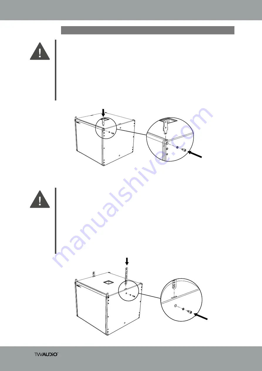
4.14 Preparing a subwoofer for a flown system
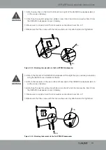
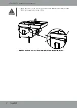
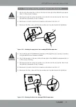
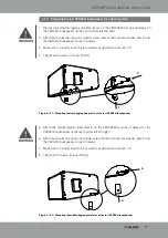
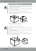
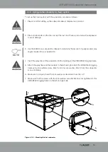
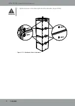
Figure 4.14.1 - Attaching the splay links to the subwoofers
WARNING
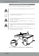
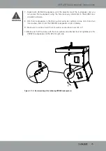
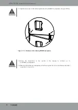
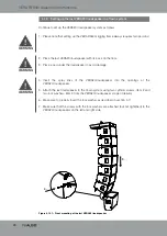
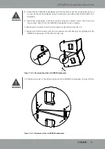
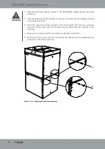
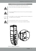
Figure 4.14.2 - Attaching the brackets to the subwoofer
WARNING
1.
2.
7.
5.
1. Start by attaching splay links on the front top left and right of the subwoofer (item 1 on the
scope of delivery). Please note that the VERA S17i loudspeakers for the cardioid applica-
tion have to be according to chapter 4.19.
2. Attach each splay link using one cylinder screw, item 2 and one lock washer, item 3 from
the subwoofer scope of delivery.
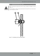
3. Make sure to properly insert the lock washer as described in section 4.7!
4. Make sure that the screws with the lock washers are attached (but not tightened) to the
subwoofer on the left and right side.
5. Turn the bracket and attach it to the subwoofer (hole F).
6. Attach the brackets to the middle top left and right of the subwoofer (item 4 on the scope
of delivery).
7. Attach each brackets using one cylinder screw, item 2 and one lock washer, item 3 from
the subwoofer scope of delivery.
8. Make sure to properly insert the lock washer as described in section 4.7!
9. Make sure that the screws with the lock washers are attached (but not tightened) to the
subwoofer on the left and right side.

