6
SAFETY AND OPERATING INSTRUCTIONS
89200016
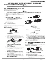
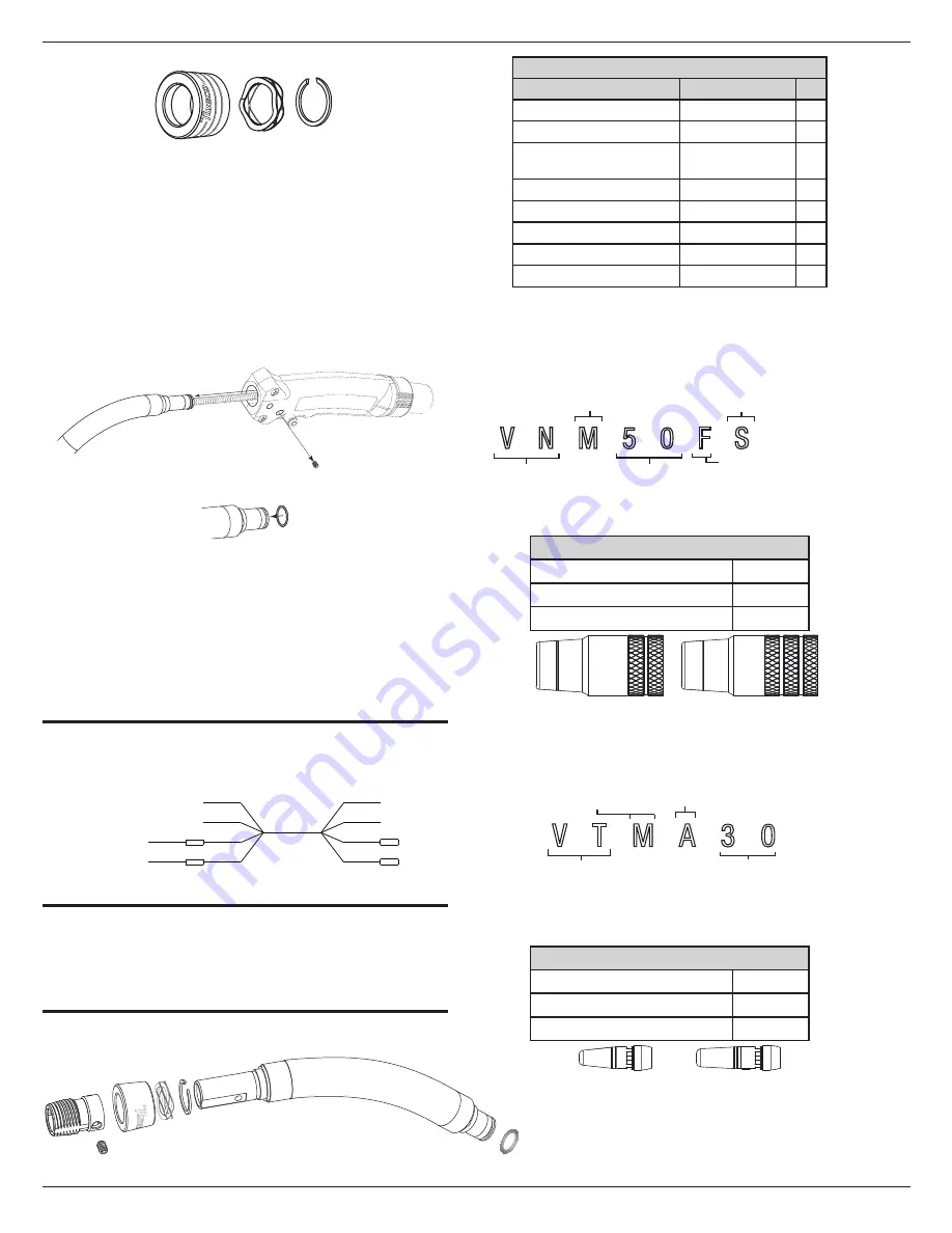
Lock Collar
Spring Washer
Snap Ring
4. Slide the Stainless Steel Sleeve onto the conductor tube end.
5. Align the set screw with the threaded hole in the conductor tube and tighten
until the screw bottoms out. Do not overtighten.
The conductor tube Stainless Steel Sleeve replacement is complete. Trim the
conduit and install the consumables.
5.04
REPLACE CONDUCTOR TUBE
The conductor tube is attached to the MIG Gun handle by two set screws on the side of the
handle. To remove:
1. Remove the front end consumables from the conductor tube.
Loosen the conduit liner set screw with a 5/64" hex wrench supplied and then
loosen the socket head cap screw securing the conductor tube in place inside
the handle with a 5/32" hex wrench. Refer to the figure below.
2. Remove conductor tube.
Conductor Tube set screw
3. Mount the conductor tube O-ring on the end of the conductor tube.
Slide the tube over the liner and insert into the brass connection within the
handle. Tighten the socket head cap screw wrench tight using the 5/32" hex
wrench.
4. Tighten the conduit set screw down against the liner. Do not overtighten to
avoid damages the liner.
5. Check the length of conduit extending from the conductor tube front end and
adjust if necessary.
There are two methods of trimming the conduit. See "Conduit Installation" on
page 5.
SECTION 6: CABLEHOZ® REPAIR
6.01
CABLEHOZ® REPAIR
If you should find it necessary to repair Cablehoz connection(s), repair instructions can be
found at
www.Tweco.com
our website.
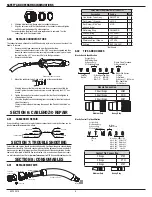
RED
WHITE
BLACK
BLACK
RED
WHITE
BLACK
BLACK
TRIGGER
NOT USED
NOT USED
BLUE
BROWN
CONTROL WIRE
CABLEHOZ
{
SECTION 7: TROUBLESHOOTING
Contact tips and nozzles should be cleaned frequently. Spatter buildup may cause bridging
between nozzle and tip. This could cause electrical shorting between the nozzle and work
piece as well as poor or improper gas flow. Regularly inspect the conductor tube, handle,
cable, and other parts of the MIG Gun for abrasion, cuts, or undue wear. Replace or repair
any parts found deficient. Refer to
www.Tweco.com
for MIG Gun troubleshooting chart(s).
SECTION 8: CONSUMABLES
8.01
REPLACEMENT KITS
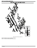
Conductor Tube
O-ring
Set Screw
Retaining Ring
Wave Spring
Stainless
Steel Sleeve
Lock Collar
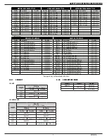
Spray Master Replacement
Kit Parts List
Description
Part No.
Qty
Conductor Tube Assy.
SMVCT60
1
Set Screw* (Sleeve)
V41CS
1
Set Screw (5/64" hex
wrench drive)
41CS
1
Retaining Ring
PMA64RS
1
Wave Spring
VCTLSPR
4
Lock Collar
VCTLSLK
1
Stainless Steel Sleeve
VCTLSL
1
O-Ring
94-710-036S
1
* Not Shown
8.02
TIPS AND NOZZLES
Velocity Nozzle Identification
V N M 5 0 F S
Velocity
Nozzle
Blank=Std Recess
F=Flush
P=Protrude
R= Recess ¼” (6.35mm)
FAS=Spot Weld
FC=Flux Core
S=Light Duty
M=Medium Duty
H=Heavy Duty
ET=Extended Taper
Orifice Opening Size:
37
=3/8”
62
=5/8”
50
=1/2”
75
=3/4”
Blank= Fixed Threaded
S=Adjustable Slip
Nozzle Convention
2 Knurl Rings
VNM
3 Knurl Rings
VNH
4 Knurl Rings
VNET
Medium Duty Heavy Duty
Velocity Contact Tip Identification
V T M A 3 0
Velocity
Tip
S=Light Duty
M=Medium Duty
H=Heavy Duty
ET=Extended Taper
A=Alum
Blank=Other
Wire Size:
364
=3/64”
23
=0.023”
116
=1/16”
30
=0.030”
564
=5/64”
35
=0.035”
332
=3/32”
40
=0.040”
764
=7/64”
45
=0.045”
18
=1/8”
Contact Tip Convention
2 Rings
VTM
3 Rings
VTH
4 Rings
VTET
Medium Duty Heavy Duty


