background image

TW-SP245 MANUAL


state: 14.03.2019 


page 

2

 of 

12


Table of contents 

1.  Important Information   


  2 

2.  Specification 


  3 

3.  Prepare before using 


  3 

4.  Maintenance 


  4 

5.  Spare parts   


  6 

6.  CE-certificate   


11 


Operation Manual 

1.  Important Information   
1.1 Safety Information   
1.1.1 Hazard Symbols Used in the Manuals   

This manual includes the hazard symbols defined below when the operations or 
maintenance job involves a potential danger. These symbols describe the level of danger 
involved in performing a job on the tool and the precautions to take to avoid the hazard. 


1.1.2 Safety Requirements   
Important   

Make sure to read, understand, and strictly follow all safety related instructions before 
operation or maintenance of this equipment.   

Intended Users 


This manual is to be made available to all persons who are required to install, configure or 
service equipment described herein, or any other associated operation. 


Application Area   

The machinery described is intended for machinery production and assembling spare parts. 
It is used to press, size, assemble, rivet small parts in process and not for other use.   

Personnel   

Installation, operation and maintenance of the equipment should be carried out by qualified 
personnel. A qualified person is someone who is technically competent and familiar with 
all safety information and established safety practices with the  installation process, 
operation and maintenance of this equipment; and with all the hazards involved. 


Summary of Contents for TWSP245

Page 1: ......

Page 2: ...trictly follow all safety related instructions before operation or maintenance of this equipment Intended Users This manual is to be made available to all persons who are required to install configure or service equipment described herein or any other associated operation Application Area The machinery described is intended for machinery production and assembling spare parts It is used to press si...

Page 3: ...ct a certified technical support engineers for repair The equipment must not be operated without approval from the certified technical support engineer 2 Specification 2 1 Application Area The machinery described is intended for machinery production and assembling spare parts It is used to press size assemble rivet small parts in process and not for other use 2 2 Mechanical part No Item Unit Value...

Page 4: ... Users should provide enough space for the equipment and the environment should be clean non flammable corrosive and dust free A working area of 1 000mm is to be kept free both in front of and behind the machine while it is in operation so that it is always easily accessible ...

Page 5: ... shaft assembly the joints and all moving parts with a light oil in normal service DO NOT allow lubricant to heel block nor frame of shop press When not in use store the press in a dry location with ram and piston fully retracted When press efficiency drops purge away air from the hydraulic system as described before Check the hydraulic oil remove the oil filler nut on the top of the reservoir if ...

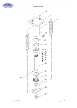
Page 6: ...TW SP245 MANUAL state 14 03 2019 page 6 of 12 5 Spare parts 5 1 Exploded views ...

Page 7: ...TW SP245 MANUAL state 14 03 2019 page 7 of 12 ...

Page 8: ...TW SP245 MANUAL state 14 03 2019 page 8 of 12 ...

Page 9: ...G RING 4 14 RAM ASSY 1 40 WIRE ROPE 1 15 WASHER 4 41 BIG ROLLER 1 16 LOCK WASHER 4 42 HANDLE WINCH 1 17 NUT 4 43 NUT 3 18 PIN 2 44 FISED PLATE 1 19 LOWER CROSS MEMBER 1 45 BOLT 3 20 BOLT 4 46 CONNECTOR 3 21 WASHER 7 47 BLOCKS 2 22 O RING 4 48 RETAINING RING 4 23 HOSE 1 1 49 SHIELD 1 1 24 PRESSURE GAUGE 1 50 SHIELD 2 1 25 NUT 1 51 SHIELD 3 3 26 NYLON RING 1 52 SHIELD 4 3 Part No Description Qty Par...

Page 10: ...P19 SPRING 3 P46 R PIN 1 P20 SPRING 2 P47 STEEL BALL 2 P21 VALVE SEAT 2 P48 NYLON RING 1 P22 STEEL BALL SEAT 2 P49 CONNECTOR 1 P23 STEEL BALL SEAT 1 P50 O RING 1 P24 SPRING 2 P51 HANDLE 1 P25 SPRING 1 P52 HOSE 1 P26 SCREWS 2 P53 CONNECTOR 1 P27 O RING 3 Part No Description Qty Part No Description Qty R01 PIN 2 R10 VALVE ROD 1 R02 RAM 1 R11 NYLON RING 1 R03 SPRING 2 R12 SCREW 1 R04 CONNECT 1 R13 PI...

Page 11: ...TW SP245 MANUAL state 14 03 2019 page 11 of 12 ...

Page 12: ...TW SP245 MANUAL state 14 03 2019 page 12 of 12 ...

Reviews: