background image

Twin City IM-4050

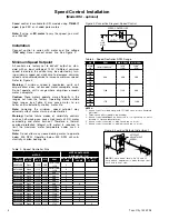
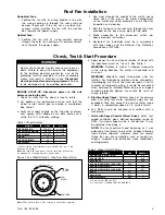
Figure 3. Low End Setpoint Adjustment

NOTE:

 5 amp model shown. On 10 and 15 

amp models, adjustment is made through clear-

ance hole in heat sink.

SETPOINT

ADJUSTMENT

SCREW

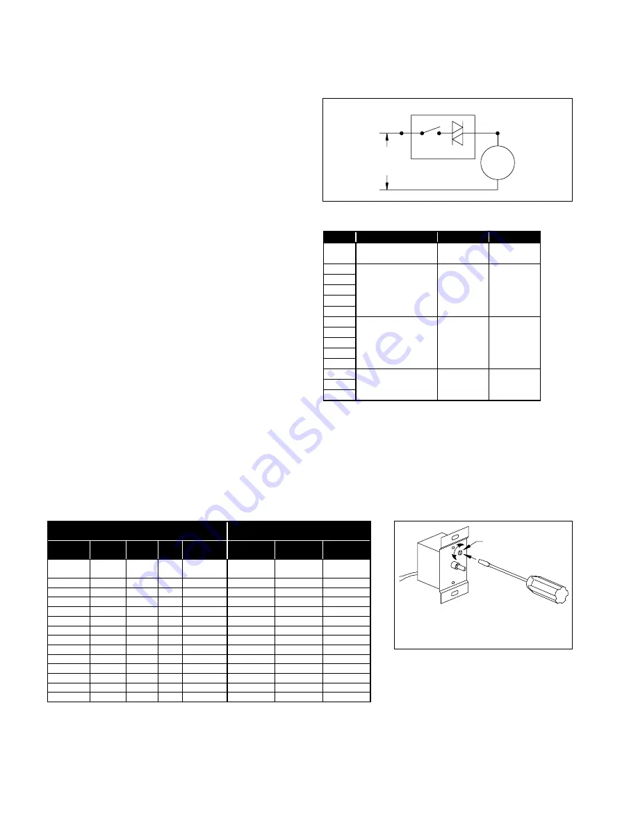
Table 4. Speed Controller Size

Speed Control Installation 

(Models DCLH, DCLP, DCRD, DCRU, DCRUR, DCRW, DCRWR - optional)

Speed  control  is  available  using 

115/60/1  open

  type 

PSC or shaded pole motors.

Installation

Connect  control  in  series  with  motor  and  line  voltage 

(

115V only

). Never connect across line. See Figure 2.

Minimum Speed Setpoint

All controls are factory set to 65V±3V output as stan-

dard with an input voltage of 120V. If different minimum 

speed is desired, the control may be adjusted by turn-

ing minimum speed pot clockwise to decrease minimum 

speed and counterclockwise to increase minimum speed. 

Refer to Figure 3.

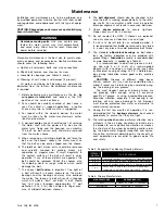
Warning:

  If  minimum  speed  is  readjusted,  verify  unit 

ampere draw does not exceed motor nameplate amps. 

Do not operate unit in range where amp draw exceeds 

motor nameplate.

Caution:

  These  motors  operate  more  efficiently  in  the 

ranges  set  from  the  factory.  Operating  motor  outside 

these  ranges  (see  Table  3)  may  cause  motor  to  run 

hotter and substantially shorten motor life.

Note:

  Lowering  the  minimum  speed  setpoint  may 

adversely affect motor start-up characteristics.

Warning:

  Certain  failure  modes  of  solid-state  controls 

such as half-waving can cause high levels of DC, motor 

overheating  and  motor  burn-out.  Therefore,  a  thermal 

overload  protection  (integral  with  motor)  is  required  to 

limit  the  maximum  motor  temperature  under  such  a 

failure.

Note:

 Do not allow any sleeve bearing motor to operate 

below  500  RPM.  Operation  below  500  RPM  will  sub-

stantially shorten bearing life.

Figure 2. Connection Diagram, Speed Control

SPEED CONTROLLER

AC

LINE

(115V)

SWITCH TRI-AC

MOTOR

Table 3. Speed Controller RPM Range

HP

RPM

MAX. RPM

MIN. RPM

1/30

1650/1500/1350

2,3

1650

4

1300

4

1/8

1500

5

950

5

1/15

860

860

500

1/8
1/6
1/4
1/2
1/8

1140

1140

900

1/6
1/4
1/2

1

1/3

1725

1725

1200

1/2
3/4

NOTES:

• 

Speed control available 

only

 with 115/60/1 open motors (thermally 

protected).

• 

Three-speed motor (multiple tap winding).

• 

Speed control 

should not

 be connected to low speed tap on motor 

because of starting characteristics.

• 

Speed control connected to high speed tap on motor.

• 

Speed control connected to medium speed tap on motor.

MOTOR

SPEED CONTROLLER 

DESIGNATION / FLA

PART 

NUMBER

ENCLO-

SURE

VOLT-

AGE

HP

RPM

KBWC-15K 

5 AMP

KBWC-110 

10 AMP

KBWC-115 

15 AMP

66543600

Open

115V

1/8

1650/1500/

1350

X

66804500

Open

115V

1/15

860

X

66543700

Open

115V

1/8

860

X

67123100

Open

115V

1/6

860

X

66543800

Open

115V

1/4

860

X

66543900

Open

115V

1/2

860

X

66804600

Open

115V

1/8

1140

X

67125100

Open

115V

1/6

1140

X

66544000

Open

115V

1/4

1140

X

66544100

Open

115V

1/2

1140

X

66544200

Open

115V

1

1140

X

66544300

Open

115V

1/3

1725

X

66544400

Open

115V

1/2

1725

X

67122500

Open

115V

3/4

1725

X

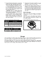
Summary of Contents for BAE

Page 1: ...ur air moving equip ment A variety of safety devices are available It is the user s responsibility to determine adequate safety measures and to obtain the required safety equipment Shipping and Receiving All Twin City Fan Blower products are carefully con structed and inspected before shipment to insure the highest standards of quality and performance Compare all components with the bill of lading...

Page 2: ...eft at approximately 180 degrees from that of the previous month to prevent the shaft and impeller from taking a set in one position Storage records should be maintained which indicate the above requirements have been followed Consult the motor manufacturer for proper storage space heater connection and lubrication if the unit was supplied with one Start Up When the unit is removed from storage al...

Page 3: ...ing should be perpendicular and the bearing base parallel to the axis of the shaft to prevent loads caused by misalign ment e Mount assembly bolt bearings to drive stand Shaft Figure 3 Drive Component Assembly must be parallel with side of bearing pedestal Precision shim bearings as required After aligning and bolting bearings to pedestal lock bearings Be sure expansion bearing if supplied is set ...

Page 4: ...person and the key to be retained by this person to prevent accidental power of the fan while service is in process A DIA B RBO RBR B B B A B A B A SWSI DWDI Figure 7 Wheel Funnel Overlap HIB RTF HRT Wheel Placement Size A B B Size A B B 19 23 19 23 180 20 50 0 31 400 45 25 0 69 1 03 0 97 200 22 50 0 34 450 50 00 0 75 1 13 1 06 220 25 00 0 38 490 55 13 0 81 1 25 1 13 240 27 50 0 44 540 61 00 0 91 ...

Page 5: ...hrough the motor cooling fan Follow normal maintenance schedule given to the right Motors should be kept dry to avoid electrical short circuits Motors kept in storage for long periods of time can have moisture condense on the windings Be certain the motor is dry before using Some smaller motors are lubricated for life Motor bearing lubrication if required must follow a rigorous schedule Motors les...

Page 6: ...6 41 2 4 31 2 21 2 11 2 1 1 2 2 00 oz 75 100 47 16 thru 415 16 4 4 21 2 1 1 2 4 00 oz 110 135 57 16 thru 615 16 4 21 2 11 2 7 00 oz 140 180 Grease to be added at each interval WARNING 1 This equipment must not be operated without proper guarding of all moving parts While performing maintenance be sure remote power switches are locked off See installation manual for recom mended safety practices 2 ...

Page 7: ...plication and field measurement procedures can be found in AMCA Publications 201 and 203 Troubleshooting Performance Problems The lists below indicate possible areas to check when air or sound values do not match expectations Most fan prob lems can be pinpointed to one of these common causes Air Capacity Problems 1 Resistance of system not at design rating If resis tance is lower than expected bot...

Page 8: ...and operate satisfactorily if the temperature remains constant and the bearing receives adequate lubrication Remember that a roller bearing under the same load and speed will be somewhat more noisy and run warmer than a ball bearing This is normal Rough handling and or dropping a fan can result in bri nelling the bearing This appears as a clicking noise at first then gradually worsens until failur...

Page 9: ...l be shipped together Verification of shipments must be limited to only those items on the bill of lading The unit nameplate must be checked to make sure the voltage agrees with the power supply available CAUTION Sheet metal parts screws clips and similar items inherently have sharp edges and it is necessary that the installer and service personnel exercise caution The installation of this equipme...

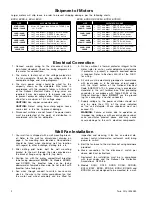
Page 10: ...power leads must be protected at the point of distribution in accordance with the fan dataplate 5 On fans without a thermal protector integral to the motor refer to unit or motor dataplate to determine if protector is present a separate overload device is required Refer to Sections 430 32 of the N E C for sizing 6 All units must be electrically grounded in accordance with local codes or in the abs...

Page 11: ...e 4 Apply power to unit and check rotation of wheel with the directional arrow on the unit See Table 1 WARNING Rotation is critical If allowed to operate in the wrong direction the motor will overload and burn out WARNING Especially check three phase units for rotation For three phase rotation can be changed by interchanging any two of the three line leads If unit is checked on temporary wiring it...

Page 12: ...uch as half waving can cause high levels of DC motor overheating and motor burn out Therefore a thermal overload protection integral with motor is required to limit the maximum motor temperature under such a failure Note Do not allow any sleeve bearing motor to operate below 500 RPM Operation below 500 RPM will sub stantially shorten bearing life Figure 2 Connection Diagram Speed Control SPEED CON...

Page 13: ... over tension as bearing damage will occur Recommended belt tension should permit 1 64 deflection per inch of span of the belt at the center of the belt span To find this point measure halfway between the pulley centerlines as shown in Figure 5 Extreme care must be exercised when adjusting V belts as not to mis align the pulleys Any misalignment will cause a sharp reduction in belt life and will a...

Page 14: ...an Blower ventilators carry a one year limited warranty from date of shipment For repairs within the warranty period the motor must be taken to the motor manufacturer s authorized service dealer Contact your representative for additional warranty details 4 A periodic motor check should consist of spinning the motor shaft with the power off to be sure the motor turns freely and the bearings run smo...

Page 15: ...s recom mended or more frequently if needed see Table 5 It is recommended to add fresh grease at start up but do not over grease Use only 1 or 2 shots of a recommended lubricant with a hand gun in most cases see Table 6 Maximum hand gun rating 40 P S I Rotate bearings during lubrication where good safety practice permits CAUTION Greases of different soap bases lithium sodium etc may not be compati...

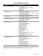
Page 16: ...alance 6 Wheel hitting housing 7 Bent shaft 8 Bearings need lubrication 9 Loose bearing bolts 10 Loose or worn bearings 11 Mismatched belts 12 Belts too loose or too tight 13 Belts oily or dirty 14 Belts worn 15 Loose fan mounting bolts 16 Rattle of components in high velocity airstream 17 Electrical noise 18 Noise from high velocity air system 19 Vibrating parts not isolated from building 20 Vibr...

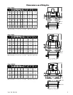
Page 17: ...0B 31 06 27 25 5 19 24 00 22 5x22 5 18x18 82 170B 39 63 29 25 4 06 30 00 28 5x28 5 24x 24 95 180B 39 63 30 25 5 06 30 00 28 5x28 5 24x24 100 SIZE FAN DIMENSIONS CANTED CURB SIZE DAMPER SIZE AVG SHIP WT LBS A B C E 070 075D 25 88 22 13 2 06 17 00 15 5x15 5 10x10 58 085D 27 88 23 94 2 38 17 00 15 5x15 5 10x10 67 100D 27 88 23 94 2 38 20 00 18 5x18 5 14x14 74 120D 30 94 28 13 2 56 20 00 18 5x18 5 14x...

Page 18: ...F FLASH CURB SIZE DCRU DCRUR 071B 073B 071B 073B 10 x 10 151 2 x 151 2 161 2 x 161 2 081B 083B 081B 083B 10 x 10 151 2 x 151 2 161 2 x 161 2 091B 093B 091B 093B 14 x 14 181 2 x 181 2 191 2 x 191 2 110B 110B 18 x 18 221 2 x 221 2 231 2 x 231 2 120B 120B 18 x 18 221 2 x 221 2 231 2 x 231 2 140B 140B 18 x 18 221 2 x 221 2 231 2 x 231 2 160B 160B 18 x 18 221 2 x 221 2 231 2 x 231 2 180B 180B 24 x 24 2...

Page 19: ...B 120B 30 00 27 19 12 00 25 56 24 00 135 17 x 17 233 4 x 233 4 171 2 x 171 2 140B 140B 30 00 27 68 12 00 25 56 24 00 145 17 x 17 233 4 x 233 4 171 2 x 171 2 160B 160B 30 00 29 81 12 00 25 56 24 00 180 17 x 17 233 4 x 233 4 171 2 x 171 2 180B 180B 36 00 29 17 18 00 31 56 30 00 180 24 x 24 293 4 x 293 4 241 2 x 241 2 MODEL A B C D E AVG SHIP WT LB DAMPER SIZE WALL MTG BRACKET WALL OPENING H BCRW BCR...

Page 20: ...IZE AVG SHIP WT LBS 100 17 75 38 63 28 00 3 00 20 00 10 00 181 2 x 181 2 14 x 14 110 120 18 50 38 63 28 00 3 75 20 00 10 00 181 2 x 181 2 14 x 14 113 140 19 81 39 13 35 00 4 00 24 00 9 38 221 2 x 221 2 18 x 18 126 160 20 25 39 13 35 00 4 38 26 00 9 38 241 2 x 241 2 20 x 20 131 180 21 13 51 13 40 00 4 38 30 00 10 50 281 2 x 281 2 24 x 24 168 210 23 13 51 13 43 00 5 00 30 00 12 00 281 2 x 281 2 24 x...

Page 21: ... DAMPER SIZE AVG SHIP WT LBS 100 19 88 38 50 28 00 12 19 20 00 181 2 x 181 2 14 x 14 87 120 20 63 38 50 28 00 12 19 20 00 181 2 x 181 2 14 x 14 89 140 20 88 40 00 32 00 11 00 24 00 221 2 x 221 2 18 x 18 95 160 21 25 40 00 32 00 11 00 26 00 241 2 x 241 2 20 x 20 107 180 24 50 46 00 36 00 11 00 30 00 281 2 x 281 2 24 x 24 128 210 25 13 46 00 38 00 12 50 30 00 281 2 x 281 2 24 x 24 138 240 29 38 49 5...

Page 22: ... makes no warranty express or implied with respect to motors switches controls or other components of seller s product where such components are warranted separately by their respective manufac turers THIS WARRANTY IS EXPRESSLY IN LIEU OF ALL OTHER WARRANTIES EXPRESS OR IMPLIED WHETHER STATUTORY OR OTHERWISE INCLUDING ANY IMPLIED WARRANTY OF MERCHANTABILITY OR FITNESS FOR A PARTICULAR PURPOSE In n...

Page 23: ...Twin City IM 4050 15 Refer to pages 6 and 7 for recommended maintenance ...

Page 24: ...5MWG10 14 TWIN CITY FAN BLOWER WWW TCF COM 5959 Trenton Lane N Minneapolis MN 55442 Phone 763 551 7600 Fax 763 551 7601 ...

Page 25: ...ur air moving equip ment A variety of safety devices are available It is the user s responsibility to determine adequate safety measures and to obtain the required safety equipment Shipping and Receiving All Twin City Fan Blower products are carefully con structed and inspected before shipment to insure the highest standards of quality and performance Compare all components with the bill of lading...

Page 26: ...eft at approximately 180 degrees from that of the previous month to prevent the shaft and impeller from taking a set in one position Storage records should be maintained which indicate the above requirements have been followed Consult the motor manufacturer for proper storage space heater connection and lubrication if the unit was supplied with one Start Up When the unit is removed from storage al...

Page 27: ...ing should be perpendicular and the bearing base parallel to the axis of the shaft to prevent loads caused by misalign ment e Mount assembly bolt bearings to drive stand Shaft Figure 3 Drive Component Assembly must be parallel with side of bearing pedestal Precision shim bearings as required After aligning and bolting bearings to pedestal lock bearings Be sure expansion bearing if supplied is set ...

Page 28: ...person and the key to be retained by this person to prevent accidental power of the fan while service is in process A DIA B RBO RBR B B B A B A B A SWSI DWDI Figure 7 Wheel Funnel Overlap HIB RTF HRT Wheel Placement Size A B B Size A B B 19 23 19 23 180 20 50 0 31 400 45 25 0 69 1 03 0 97 200 22 50 0 34 450 50 00 0 75 1 13 1 06 220 25 00 0 38 490 55 13 0 81 1 25 1 13 240 27 50 0 44 540 61 00 0 91 ...

Page 29: ...hrough the motor cooling fan Follow normal maintenance schedule given to the right Motors should be kept dry to avoid electrical short circuits Motors kept in storage for long periods of time can have moisture condense on the windings Be certain the motor is dry before using Some smaller motors are lubricated for life Motor bearing lubrication if required must follow a rigorous schedule Motors les...

Page 30: ...6 41 2 4 31 2 21 2 11 2 1 1 2 2 00 oz 75 100 47 16 thru 415 16 4 4 21 2 1 1 2 4 00 oz 110 135 57 16 thru 615 16 4 21 2 11 2 7 00 oz 140 180 Grease to be added at each interval WARNING 1 This equipment must not be operated without proper guarding of all moving parts While performing maintenance be sure remote power switches are locked off See installation manual for recom mended safety practices 2 ...

Page 31: ...plication and field measurement procedures can be found in AMCA Publications 201 and 203 Troubleshooting Performance Problems The lists below indicate possible areas to check when air or sound values do not match expectations Most fan prob lems can be pinpointed to one of these common causes Air Capacity Problems 1 Resistance of system not at design rating If resis tance is lower than expected bot...

Page 32: ...and operate satisfactorily if the temperature remains constant and the bearing receives adequate lubrication Remember that a roller bearing under the same load and speed will be somewhat more noisy and run warmer than a ball bearing This is normal Rough handling and or dropping a fan can result in bri nelling the bearing This appears as a clicking noise at first then gradually worsens until failur...

Page 33: ... carrier Physical damage to the unit after acceptance is not the responsibility of Twin City Fan Companies Ltd Unpack each carton or crate and verify that all required parts and proper quantities of each item have been received Refer to drawings for part descriptions Report shortages or missing items to your local representative to arrange for replacement parts Due to availability of carriers and ...

Page 34: ... to increase wire size to prevent excessive voltage drop Wires should be sized for a maximum of 3 voltage drop CAUTION Use copper conductors only CAUTION Protect wiring from sharp edges Leave some slack in the line to prevent damage 4 Disconnect switches are not fused The power leads must be protected at the point of distribution in accordance with the fan dataplate 5 On fans without a thermal pro...

Page 35: ...hase rotation can be changed by interchanging any two of the three line leads If unit is checked on temporary wiring it should be rechecked when permanently installed Motor burn out or tripped overload protec tion devices are usually the result of wrong rotation 5 Electrical Input Check Perform check of fan ampere draw and verify that motor nameplate amps are not exceeded Take into account the ser...

Page 36: ...h as half waving can cause high levels of DC motor overheating and motor burn out Therefore a thermal overload protection integral with motor is required to limit the maximum motor temperature under such a failure Note Do not allow any sleeve bearing motor to operate below 500 RPM Operation below 500 RPM will sub stantially shorten bearing life Figure 2 Connection Diagram Speed Control SPEED CONTR...

Page 37: ...ver tension as bearing damage will occur Recommended belt tension should permit 1 64 deflection per inch of span of the belt at the center of the belt span To find this point measure halfway between the pulley centerlines as shown in Figure 5 Extreme care must be exercised when adjusting V belts as not to mis align the pulleys Any misalignment will cause a sharp reduction in belt life and will als...

Page 38: ...al on wheel 4 Worn or corroded wheel 5 Wheel out of balance 6 Wheel hitting housing 7 Bent shaft 8 Bearings need lubrication 9 Loose bearing bolts 10 Loose or worn bearings 11 Mismatched belts 12 Belts too loose or too tight 13 Belts oily or dirty 14 Belts worn 15 Loose fan mounting bolts 16 Rattle of components in high velocity airstream 17 Electrical noise 18 Noise from high velocity air system ...

Page 39: ... when subject to finger pres sure at midpoint between sheaves 8 The belt alignment should also be checked to be sure the belt is running perpendicularly to the rotat ing shafts Fan and motor shafts must be parallel Improper alignment will result in excessive belt wear 9 Check sheave setscrews to ensure tightness Proper keys must be in keyways 10 Do not readjust fan RPM If sheaves are replaced use ...

Page 40: ... 88 245A 245AHP 36 50 37 50 32 88 1 50 35 00 40 38 20 20 35 31 18 50 33 00 x 33 00 352 27 88 x 31 88 270A 270AHP 39 00 40 13 35 88 1 50 37 50 43 00 21 45 37 88 20 00 36 00 x 36 00 394 29 88 x 33 88 300A 300AHP 41 50 44 13 39 88 1 50 39 50 47 62 23 83 41 88 20 00 40 00 x 40 00 442 29 88 x 37 88 330A 330AHP 45 50 48 81 43 88 1 50 43 50 52 31 26 19 46 56 20 00 44 00 x 44 00 554 31 88 x 39 88 365A 365...

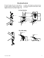
Page 41: ...on page 8 The 9 16 holes in these brackets can readily be used for installing the units To obtain optimum isolation the BSI unit should be installed with the motor above or below the fan body Floor Mounting Overhead Mounting HANGER ROD NUTS WASHERS BY INSTALLER HANGER HOUSING BOLT NUTS WASHERS INCLUDED HANGER BRACKET BSI DSI UNIT NEOPRENE ISOLATOR 2 72 2 15 5 25 3 69 3 00 BSI DSI UNIT SPRING ISOLA...

Page 42: ...8 11 88 12 x 12 11 88 11 88 12 x 12 100 100 13 88 13 88 14 x 14 13 88 13 88 14 x 14 120 120 15 88 15 88 16 x 16 15 88 15 88 16 x 16 135 135 17 88 17 88 18 x 18 17 88 17 88 18 x 18 150 150 19 88 19 88 20 x 20 19 88 19 88 20 x 20 165 165 22 88 22 88 23 x 23 22 88 22 88 23 x 23 180 23 88 23 88 24 x 24 23 88 23 88 24 x 24 210 27 88 27 88 28 x 28 27 88 27 88 28 x 28 225 25 88 28 88 26 x 29 29 88 29 88 ...

Page 43: ...Twin City IM 4205 11 Refer to page 7 for recommended maintenance ...

Page 44: ...n that such defects have not been caused by misuse neglect improper installation repair alteration act of God or accident No warranty made hereunder shall extend to any seller product whose serial number is altered effaced or removed Seller makes no warranty express or implied with respect to motors switches controls or other components of seller s product where such components are warranted separ...

Page 45: ...l be shipped together Verification of shipments must be limited to only those items on the bill of lading The unit nameplate must be checked to make sure the voltage agrees with the power supply available CAUTION Sheet metal parts screws clips and similar items inherently have sharp edges and it is necessary that the installer and service personnel exercise caution The installation of this equipme...

Page 46: ...power leads must be protected at the point of distribution in accordance with the fan dataplate 5 On fans without a thermal protector integral to the motor refer to unit or motor dataplate to determine if protector is present a separate overload device is required Refer to Sections 430 32 of the N E C for sizing 6 All units must be electrically grounded in accordance with local codes or in the abs...

Page 47: ...e 4 Apply power to unit and check rotation of wheel with the directional arrow on the unit See Table 1 WARNING Rotation is critical If allowed to operate in the wrong direction the motor will overload and burn out WARNING Especially check three phase units for rotation For three phase rotation can be changed by interchanging any two of the three line leads If unit is checked on temporary wiring it...

Page 48: ...uch as half waving can cause high levels of DC motor overheating and motor burn out Therefore a thermal overload protection integral with motor is required to limit the maximum motor temperature under such a failure Note Do not allow any sleeve bearing motor to operate below 500 RPM Operation below 500 RPM will sub stantially shorten bearing life Figure 2 Connection Diagram Speed Control SPEED CON...

Page 49: ... over tension as bearing damage will occur Recommended belt tension should permit 1 64 deflection per inch of span of the belt at the center of the belt span To find this point measure halfway between the pulley centerlines as shown in Figure 5 Extreme care must be exercised when adjusting V belts as not to mis align the pulleys Any misalignment will cause a sharp reduction in belt life and will a...

Page 50: ...an Blower ventilators carry a one year limited warranty from date of shipment For repairs within the warranty period the motor must be taken to the motor manufacturer s authorized service dealer Contact your representative for additional warranty details 4 A periodic motor check should consist of spinning the motor shaft with the power off to be sure the motor turns freely and the bearings run smo...

Page 51: ...s recom mended or more frequently if needed see Table 5 It is recommended to add fresh grease at start up but do not over grease Use only 1 or 2 shots of a recommended lubricant with a hand gun in most cases see Table 6 Maximum hand gun rating 40 P S I Rotate bearings during lubrication where good safety practice permits CAUTION Greases of different soap bases lithium sodium etc may not be compati...

Page 52: ...alance 6 Wheel hitting housing 7 Bent shaft 8 Bearings need lubrication 9 Loose bearing bolts 10 Loose or worn bearings 11 Mismatched belts 12 Belts too loose or too tight 13 Belts oily or dirty 14 Belts worn 15 Loose fan mounting bolts 16 Rattle of components in high velocity airstream 17 Electrical noise 18 Noise from high velocity air system 19 Vibrating parts not isolated from building 20 Vibr...

Page 53: ...0B 31 06 27 25 5 19 24 00 22 5x22 5 18x18 82 170B 39 63 29 25 4 06 30 00 28 5x28 5 24x 24 95 180B 39 63 30 25 5 06 30 00 28 5x28 5 24x24 100 SIZE FAN DIMENSIONS CANTED CURB SIZE DAMPER SIZE AVG SHIP WT LBS A B C E 070 075D 25 88 22 13 2 06 17 00 15 5x15 5 10x10 58 085D 27 88 23 94 2 38 17 00 15 5x15 5 10x10 67 100D 27 88 23 94 2 38 20 00 18 5x18 5 14x14 74 120D 30 94 28 13 2 56 20 00 18 5x18 5 14x...

Page 54: ...F FLASH CURB SIZE DCRU DCRUR 071B 073B 071B 073B 10 x 10 151 2 x 151 2 161 2 x 161 2 081B 083B 081B 083B 10 x 10 151 2 x 151 2 161 2 x 161 2 091B 093B 091B 093B 14 x 14 181 2 x 181 2 191 2 x 191 2 110B 110B 18 x 18 221 2 x 221 2 231 2 x 231 2 120B 120B 18 x 18 221 2 x 221 2 231 2 x 231 2 140B 140B 18 x 18 221 2 x 221 2 231 2 x 231 2 160B 160B 18 x 18 221 2 x 221 2 231 2 x 231 2 180B 180B 24 x 24 2...

Page 55: ...B 120B 30 00 27 19 12 00 25 56 24 00 135 17 x 17 233 4 x 233 4 171 2 x 171 2 140B 140B 30 00 27 68 12 00 25 56 24 00 145 17 x 17 233 4 x 233 4 171 2 x 171 2 160B 160B 30 00 29 81 12 00 25 56 24 00 180 17 x 17 233 4 x 233 4 171 2 x 171 2 180B 180B 36 00 29 17 18 00 31 56 30 00 180 24 x 24 293 4 x 293 4 241 2 x 241 2 MODEL A B C D E AVG SHIP WT LB DAMPER SIZE WALL MTG BRACKET WALL OPENING H BCRW BCR...

Page 56: ...IZE AVG SHIP WT LBS 100 17 75 38 63 28 00 3 00 20 00 10 00 181 2 x 181 2 14 x 14 110 120 18 50 38 63 28 00 3 75 20 00 10 00 181 2 x 181 2 14 x 14 113 140 19 81 39 13 35 00 4 00 24 00 9 38 221 2 x 221 2 18 x 18 126 160 20 25 39 13 35 00 4 38 26 00 9 38 241 2 x 241 2 20 x 20 131 180 21 13 51 13 40 00 4 38 30 00 10 50 281 2 x 281 2 24 x 24 168 210 23 13 51 13 43 00 5 00 30 00 12 00 281 2 x 281 2 24 x...

Page 57: ... DAMPER SIZE AVG SHIP WT LBS 100 19 88 38 50 28 00 12 19 20 00 181 2 x 181 2 14 x 14 87 120 20 63 38 50 28 00 12 19 20 00 181 2 x 181 2 14 x 14 89 140 20 88 40 00 32 00 11 00 24 00 221 2 x 221 2 18 x 18 95 160 21 25 40 00 32 00 11 00 26 00 241 2 x 241 2 20 x 20 107 180 24 50 46 00 36 00 11 00 30 00 281 2 x 281 2 24 x 24 128 210 25 13 46 00 38 00 12 50 30 00 281 2 x 281 2 24 x 24 138 240 29 38 49 5...

Page 58: ... makes no warranty express or implied with respect to motors switches controls or other components of seller s product where such components are warranted separately by their respective manufac turers THIS WARRANTY IS EXPRESSLY IN LIEU OF ALL OTHER WARRANTIES EXPRESS OR IMPLIED WHETHER STATUTORY OR OTHERWISE INCLUDING ANY IMPLIED WARRANTY OF MERCHANTABILITY OR FITNESS FOR A PARTICULAR PURPOSE In n...

Page 59: ...Twin City IM 4050 15 Refer to pages 6 and 7 for recommended maintenance ...

Page 60: ...5MWG10 14 TWIN CITY FAN BLOWER WWW TCF COM 5959 Trenton Lane N Minneapolis MN 55442 Phone 763 551 7600 Fax 763 551 7601 ...

Page 61: ...s for draw down Each bolt should be placed in a sleeve or pipe with diameter larger than the bolt to allow for adjustment When the mounting surface and the surface of the fan base do not match shim level Do not distort the fan when tightening the anchor bolts A fan mounted to or within a structure should be placed as close as possible to a rigid member such as a wall or a column The structure must...

Page 62: ...derneath it The top nuts should then be tightened to hold the motor plate in place On the saddle type motor mount the motor pivots on one side and adjustment of belt tension is achieved by loosening the nuts on top of the motor plate on the other side then raising the motor plate by adjusting the nuts underneath the motor plate The nuts on top of the motor plate should again be tightened to hold t...

Page 63: ...cal shaft appli cations or for 24 hour operation Hours of operation temperature and surrounding conditions will affect the relubrication frequency required 1 Lubricate with a high quality NLGI No 2 lithium base grease hav ing rust inhibitors and antioxidant additives and a minimum oil viscosity of 500 SUS at 100 F 38 C Some greases having these properties are Shell Gadus S2 V100 2 Exxon Ronex MP M...

Page 64: ...ZE 365 402 445 490 542 600 660 730 A 44 50 49 00 54 25 60 00 66 00 73 00 80 75 89 00 B 1 13 1 25 1 38 1 56 1 69 1 88 2 09 2 28 C 15 13 16 63 18 38 20 25 22 31 24 63 27 25 30 00 Operation Checklist Verify that proper safety precautions have been followed Electrical power must be locked off Check fan mechanism components Nuts bolts setscrews are tight Mounting connections are properly made and tight...

Page 65: ...t Figure 6 Typical Horizontal Mounting with Vibration Hangers Ceiling Hung ITEM QTY DESCRIPTION 01 1 TSL or QSL Fan 02 4 Spring Hanger 03 4 Neoprene Washer 04 32 Steel Washer 05 32 Hex Nut 06 4 Threaded Rod 07 4 Hanger Rod NOTE 1 Spring hangers are optional accessories 2 Hanger rods nuts and washers supplied by customer NOTES 1 Vibration isolators are optional accessories 2 Anchor bolts and hardwa...

Page 66: ...IRFLOW 2 4 3 1 Figure 7 Typical Vertical Mounting with Vibration Hangers ITEM QTY DESCRIPTION 01 1 TSL or QSL Fan 02 4 Spring Hanger 03 4 Neoprene Washer 04 32 Steel Washer 05 32 Hex Nut 06 4 Threaded Rod 07 4 Hanger Rod NOTES 1 Spring hangers are optional accessories 2 When spring hanger interferes with ductwork add offset to threaded rod to provide clearance 3 Hanger rods nuts and washers suppli...

Page 67: ... Straightening Vanes 04 1 Discharge Cone Belt Tube Seal Removable 05 1 Housing 06 1 Motor Mount Saddle Type NOTES 1 Shaft excluded from illustration 2 Belts and driven sheave are accessible by remov ing discharge cone and belt tube seal 2 1 3 4 5 6 Figure 10 Exploded View of TSL Assembly Figure 11 Cutaway View of QSL Assembly Figure 9 Cutaway View of TSL Assembly ...

Page 68: ...nton Lane N Minneapolis MN 55442 Phone 763 551 7600 Fax 763 551 7601 1 2 3 4 5 6 NOTES 1 Shaft excluded from illustration 2 Belts and driven sheave are accessible by removing discharge cone and belt tube seal Figure 12 Exploded View of QSL Assembly ITEM QTY DESCRIPTION 01 1 Inlet Adaptor Plate and Inlet Funnel 02 1 Wheel 03 1 Bearing Housing With End Cover Plate Belt Tube Straightening Vanes 04 1 ...

Reviews: