103
Twin Disc, Incorporated
Troubleshooting
Power Transmission System Operator’s Manual #1020510
Test 1. Display Test
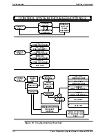
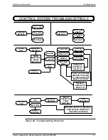
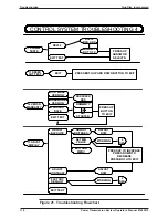
Upon entering the Troubleshooting Mode, the display test will be entered
automatically.
DISPLAY TEST
will appear. After two seconds, all display
segments/pixels will be displayed. After five seconds, the display will begin
alternating between
DISPLAY TEST
(for one second)
,
all segments/pixels (for
one second), and the firmware checksum,
CHECKSUM XXXX.
Test 1 may
be exited by depressing either the up or down arrow button. If the down arrow
button is pushed, the next display will be
2 POWER TEST
. If the up arrow
button is pushed, the next display will be
15 FAULT LOG
. Subsequently pushing
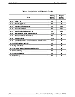
the up or down arrow button will scroll through the list of possible tests, numbered
1
through
15
(in either direction). When the desired test identifier is displayed,
the test can be entered by simultaneously depressing the up and down arrow
button.
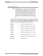
Test 2. Power Supply Test
The following sub-menu items will be displayed:
SUPPLY POWER
,
INTERNAL
POWER
,
EXIT TEST.
These are scrolled through by depressing the up or
down arrow button. To enter one of the tests, simultaneously depress both the
up and down arrow button. Once entered, the sub menu test may be exited by
pushing the up arrow button.
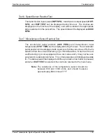
SUPPLY POWER
will display the oil well fracturing rig voltage level that is
supplied to the control with a resolution of 50 mv (.05 volts). Below 8 volts will
indicate a blank display, and above 50 volts, the display will flash 50.00 V.
INTERNAL POWER
will test five internal controller voltages. If they are all
within the allowable range, the display will show
TEST PASSED
. If any are out
of range, the display will indicate the voltage name and the word
FAILED.
The
internal voltage names are:
ANAREF
,
VSUST
,
SREFV
,
VCLAMP
, and
SNSAMPV
. The control must be replaced if one of these voltages are failed.
EXIT TEST
will return the control to the main menu at the same point that it was
when the test was entered.
Summary of Contents for TA-90-8501
Page 3: ...Document Number 1020510 Revison 1 May 2002 Power Shift Transmission System Operator s Manual ...
Page 4: ......
Page 133: ......
Page 134: ......
Page 135: ......
Page 136: ......
Page 137: ......
Page 138: ......
Page 139: ......
Page 140: ......
Page 141: ......
Page 142: ......
Page 143: ......
Page 144: ......
Page 145: ......
Page 146: ......
Page 147: ......
Page 148: ......
Page 149: ......
Page 150: ......
Page 151: ......

