106
Twin Disc, Incorporated
Troubleshooting
Power Transmission System Operator’s Manual #1020510
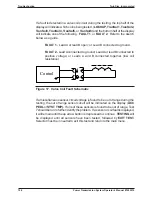
If a fault is detected in a valve coil circuit during the testing, the top half of the
display will indicate which coil is being tested, (
LOCKUP, TranSol1, TranSol2,
TranSol3, TranSol4, TranSol5,
or
TranSol6
) and the bottom half of the display
will indicate one of the following:
FAULT 1
, or
FAULT 2
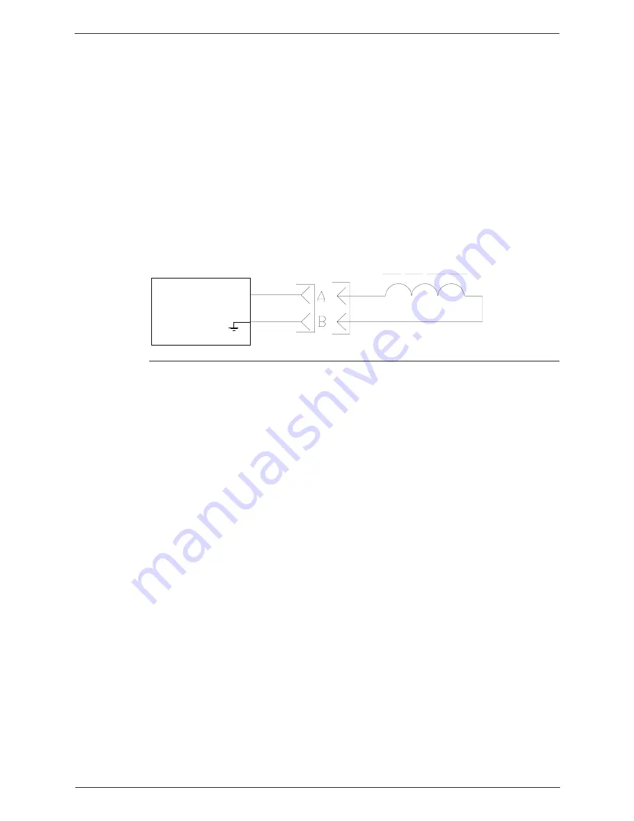
. Refer to the sketch
below as a guide.
FAULT 1
- Lead A or lead B open; or Lead B connected to ground.
FAULT 2
- Lead A connected to ground; Lead A or lead B connected to
positive voltage; or Leads A and B connected together (low coil
resistance)
Control
Figure 17. Valve Coil Fault Schematic
If a miscellaneous sensor circuit voltage is found to be out of range during the
testing, the out of range sensor circuit will be indicated on the display (
ACC
PEDL
or
SYST TMP).
If one of these sensors is found to be out of range, Test
7 should be run to further identify the problem. If a sensor or coil fault is displayed,
it will remain until the up arrow button is depressed to continue.
TESTING
will
be displayed until all sensors have been tested, followed by
EXIT TEST.
Selector must be in neutral to exit this test and return to the main menu.
Summary of Contents for TA-90-8501
Page 3: ...Document Number 1020510 Revison 1 May 2002 Power Shift Transmission System Operator s Manual ...
Page 4: ......
Page 133: ......
Page 134: ......
Page 135: ......
Page 136: ......
Page 137: ......
Page 138: ......
Page 139: ......
Page 140: ......
Page 141: ......
Page 142: ......
Page 143: ......
Page 144: ......
Page 145: ......
Page 146: ......
Page 147: ......
Page 148: ......
Page 149: ......
Page 150: ......
Page 151: ......

