88
Twin Disc, Incorporated
Troubleshooting
Power Transmission System Operator’s Manual #1020510
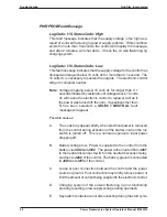
PWR PROB Fault Message
Log Code: I15, Status Code: High
This fault message indicates that the supply voltage is too high as a
result of a oil well fracturing rig power supply problem. If this condition
exists for more than 5 seconds, the control will display the message,
and after 2 minutes, will shut down. Check the oil well fracturing rig
charging system.
Log Code: I16, Status Code: Low
This fault message indicates that the supply voltage for the control has
dropped and stayed below 10 volts dc for more than 0.1 second. The
10 volts dc is necessary to sustain the outputs. The electronic control
will go to computer neutral.
Note:
Voltage dropping below 10 volts dc for longer than 0.1
seconds followed by restoration of voltage above 10 volts
dc will cause the electronic control to repower (act as if
the power was turned off, then on). If a position other than
N has been selected, a
SELECT NEUTRAL
fault
message will appear.
Possible causes:
A.
The code may appear briefly when electrical power is removed
from the control during activation of the starter
or
when the run
switch is turned off. This is a normal response to input power
dropping off.
B.
Battery voltage low. Power is supplied to the control from the
battery via
J4X2
and
J4Y2
. The power is then routed from
J2C1
to the neutral disconnect switch in the neutral disconnect relay,
and then to
J2C2
of the control. The battery ground is connected
to
J4X3
and
J4Y3
of the control.
C.
Loose or poor connection between the control and the power
source or ground. Poor connection may briefly remove power or
limit the amount of current being supplied to the electronic control.
D.
Charging system of the oil well fracturing rig not functioning
properly, resulting in low supply voltage during operation.
E.
Key switch contacts are not disconnecting during the start cycle.
Summary of Contents for TA-90-8501
Page 3: ...Document Number 1020510 Revison 1 May 2002 Power Shift Transmission System Operator s Manual ...
Page 4: ......
Page 133: ......
Page 134: ......
Page 135: ......
Page 136: ......
Page 137: ......
Page 138: ......
Page 139: ......
Page 140: ......
Page 141: ......
Page 142: ......
Page 143: ......
Page 144: ......
Page 145: ......
Page 146: ......
Page 147: ......
Page 148: ......
Page 149: ......
Page 150: ......
Page 151: ......

