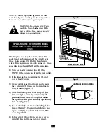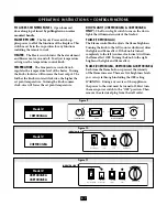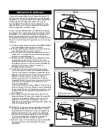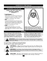
Figure 12
REMOTE CONTROL FUNCTIONS
E-8
REMOTE CONTROL FEATURES WORK SEAMLESSLY WITH CONTROL PANEL FUNCTIONS
3 FUNCTION REMOTE
23EF003GRA, 28EF003GRA & 33EF003GRA
MODELS ONLY
See Figure 12
POWER STANDBY
The Power Standby button will put the insert in a
standby mode. This will turn off all functions at
once but will hold the settings in memory. By
pressing the button again the unit will turn on
at the same settings.
HEAT
This switch will turn the power to the heater and
blower on and off. To adjust the temperature setting
you must use the temperature dimmer knob on the
control panel.
FLAME
Each time this switch is pressed, the intensity of the
ÀDPHLQFUHDVHV7KHUHDUH¿YHEULJKWQHVVOHYHOV\RX
can cycle through including the
OFF
setting.
FLA
M
E
HE
AT
POWER STANDBY
MAINTENANCE
WARNING: Make sure the power is turned off before proceeding. Any electrical repairs or
rewiring of this unit should be carried out by a licensed electrician in accordance with
national and local codes.
WARNING:
Electrical outlet wiring must comply with local building codes and other applicable
regulations to reduce the risk of fire, electrical shock and injury to persons.
WARNING:
Do not use this fireplace if any part of it has been under water. Immediately call a
qualified service technician to inspect the fireplace and replace any part of the electrical system.
WARNING:
Disconnect power before attempting any maintenance or cleaning to reduce the
risk of fire, electrical shock or personal injury.
The motors used on the fan and the flame generator
assembly are pre-lubricated for extended bearing life
and require no further lubrication. However, periodic
cleaning/vacuuming of the fan/heater unit is recom-
mended. The louvers/vent in the control door should
be cleaned periodically, both inside and out. When the
control door is in the open position the heater grill/
screen should be vacuumed. The area around the con-
trols should also be kept clean. Make sure the unit is
turned OFF and unplugged whenever you are cleaning
the heater or fireplace.
If repairing or replacing any electrical component or
wiring, the original wire routing, color coding and
securing locations must be followed.
NOTE: PLEASE OPERATE REMOTE TRANSMITTER AT A SLOW
MEASURED PACE. DEPRESS THE REMOTE CONTROL BUTTONS
WITH AN EVEN MOTION AND GENTLE PRESSURE. REPEATEDLY
PRESSING BUTTONS IN RAPID SUCCESION MAY CAUSE THE
TRANSMITTER TO MALFUNCTION


