- 12 -
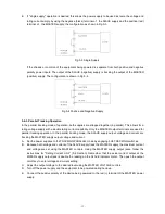
E. If "single supply" operation is desired, this allows the power supply to be used as twice the voltage and
rating current simply by using the negative (black) terminal of the SLAVE supply and the positive (red)
terminal of the MASTER supply, the configuration as shown in Fig.5-3.
Fig.5-3 Single Supply
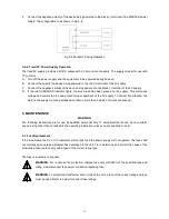
If the chassis or common of the equipment being powered is separate from both positive and negative
polarity power inputs. The output of the SLAVE (negative) supply is tracking the output of the MASTER
(positive) supply. The configuration is shown in Fig.5-4.
Fig.5-4 Positive and Negative Supply
5-4-3. Parallel Tracking Operation
In the parallel tracking mode of operation, both supplies are strapped together (in parallel). This allows for a
rating voltage supply with a double rating current capability. Only the MASTER output terminals are used for
parallel tracking operation. In the parallel tracking mode, the SLAVE supply output voltage and current are
tracking the MASTER supply output voltage and current.
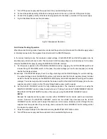
A. Set the power supplies to the TRACKING PARALLEL mode by engaging both TRACKING switches.
B. Because both voltage and current of the SLAVE supply track the MASTER supply, the maximum current
and voltage are set using the MASTER controls. Using the MASTER supply output jacks, follow the
instructions for "Setting Current Limit" (5-2 Section). Remember that the actual current output at the
MATER supply output jack is double the reading on the SLAVE indicator meter.. Then push the output
on/off key to enter voltage and current setting.
C. Adjust the output voltage to the desired level using the MASTER VOLTAGE controls.
D. Turn off the power supply and the equipment to be powered during hook-up.
E. Connect the positive polarity of the device being powered to the red (+) terminal of the MASTER power
supply.
Summary of Contents for TP-2303
Page 1: ...Multi channel DC Power Supply TP Series Operation Manual V1 0 BENCHTOP INSTRUMENT ...
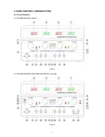
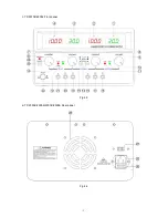
Page 7: ... 5 c TP 30102 60052 Front panel Fig 4 3 d TP 2303E 2305E 2303K 2305K Rear panel Fig 4 4 ...
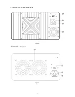
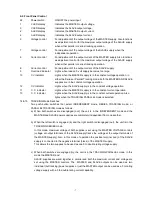
Page 8: ... 6 e TP 2303 2305 2303TK 2305TK Rear panel Fig 4 5 f TP 30102 60052 Rear panel Fig 4 6 ...


