·
Always load the rack from the bottom up. Load the heaviest component
in the rack first.
·
Make sure the rack is level and stable before pulling a component out of
the rack.
·
Make sure only one component is extended at a time. A rack might
become unstable if more than one component is extended.
To avoid damage to the equipment:
·
The rack width and depth must allow for proper serviceability and cable
management.
·
Ensure that there is adequate airflow in the rack. Improper installation or
restricted airflow can damage the equipment.
·
The rack cannot have solid or restricted airflow doors. You must use a
mesh door on the front and back of the rack or remove the doors to ensure
adequate air flow to the system.
·
If you install the Model in a rack, do not place equipment on top of the
unit. It will cause restricted airflow and might cause damage to the
equipment.
·
Make sure the product is properly matted with the rails. Products that are
improperly matted with the rails might be unstable.
·
Verify that the AC power supply branch circuit that provides power to the
rack is not overloaded. This will reduce the risk of personal injury, fire, or
damage to the equipment. The total rack load should not exceed 80
percent of the branch circuit rating. Consult the electrical authority having
jurisdiction over your facility wiring and installation requirements.
Equipment Power Cords
·
Use only the power cords and power supply units provided with your
system. The system might have one or more power cords.
·
Plug the power cord into a grounded (earthed) electrical outlet that is
Summary of Contents for GT62F-B8026
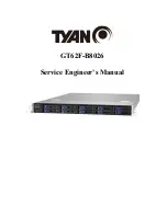
Page 1: ...GT62F B8026 Service Engineer s Manual...
Page 31: ...2 1 2 Removing the Air Duct 1 Remove the air duct from the chassis...
Page 36: ...DIMM Location...
Page 40: ...4 Insert the PCI E card in the direction of arrows as shown...
Page 41: ...5 Screw the PCI E cards firmly to the riser card bracket...
Page 46: ...http www tyan com 46 3 Secure the mounting ears of chassis to the rack with 2 M5 15L C screws...
Page 50: ...http www tyan com 50 3 4 1 Riser Card Features M7106 L16 1F Riser Card M7106 R16 1F Riser Card...
Page 53: ...http www tyan com 53 7 Remove the eight screws securing the bracket to the HDD backplane...
Page 83: ...http www tyan com 83 4 3 1 1 CPU0 Information...
Page 91: ...http www tyan com 91...
Page 107: ...http www tyan com 107 4 3 11 NVMe Configuration...
Page 108: ...http www tyan com 108 4 3 12 SATA Configuration...
Page 114: ...http www tyan com 114 4 4 1 2 Socket 0 Information...
Page 116: ...http www tyan com 116 4 5 AMD CBS Menu...
Page 118: ...http www tyan com 118 4 5 1 1 Core Thread Enablement Submenu...
Page 121: ...http www tyan com 121 4 5 3 UMC Common Options Submenu...
Page 122: ...http www tyan com 122 4 5 3 1 DDR4 Common Options Submenu...
Page 129: ...http www tyan com 129 4 5 4 FCH Common Options Submenu...
Page 134: ...http www tyan com 134 4 6 2 BMC Network Configuration Submenu...
Page 152: ...http www tyan com 152 7 Insert the LAN card into the OCP slot...
Page 153: ...http www tyan com 153 8 Secure the LAN card to the chassis...
Page 157: ...http www tyan com 157 NOTE...

