http://www.tyan.com
28
Chapter 2
Board Installation
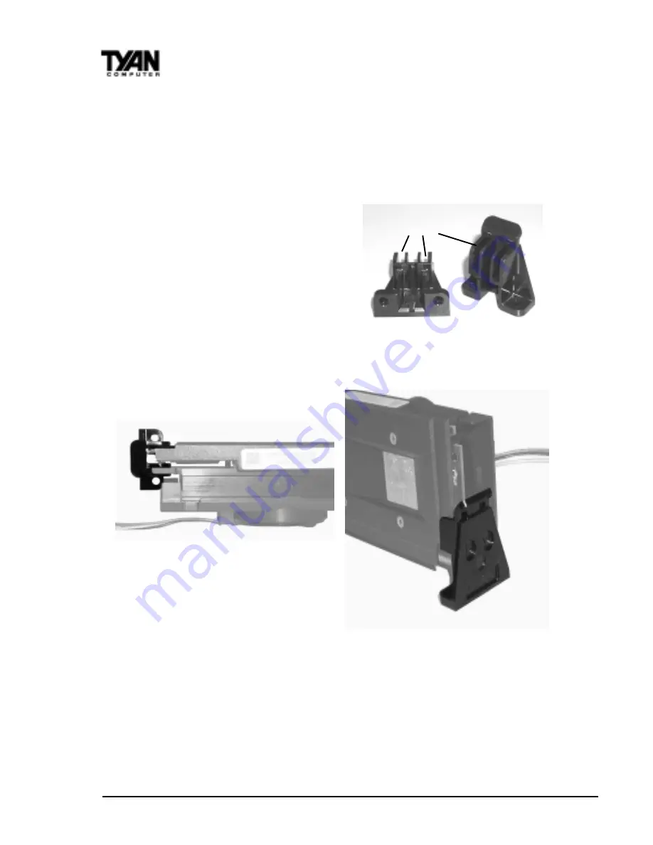
Currently, the retention module recommended for securing the SECC2 CPU
(including P-III & Celeron) is included in the motherboard package. The
retention braces consist of two small components that resemble ‘book-ends’.
(See Figure 2-17 )
The first installation step is to set the retention braces properly against the
sides of the CPU. The lower tabs of the
aluminum heat sink and the bottom Slits
corners of the plastic enclosure should
loosely fit within the two slits of the braces.
Figure 2-17
Figures 2-18 below show a top view and side view of a retention brace
positioned against one side of the SECC2 CPU.
Top View
Side View
Figure 2-18
When both braces are properly positioned, press both braces against the
sides of the CPU and carefully lift them over the CPU slot on the motherboard.
Warning - Because the braces are loosely held against the CPU, they can
easily fall off. You must hold both braces against the CPU while lifting all
three components above the motherboard. (See Figure 2-19 on the following
page.)


