background image


53 


http://www.TYAN.com 


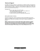
Technical Support 

 
If a problem arises with your system, you should turn to your dealer for help first. Your system has 
most likely been configured by them, and they should have the best idea of what hardware and 
software your system contains.  Furthermore, if you purchased your system from a dealer near 
you, you can bring your system to them to have it serviced instead of attempting to do so yourself 
(which can have expensive consequences). 
 
Help Resources: 

1. See the beep codes section of this manual. 
2. See the TYAN website for FAQ’s, bulletins, driver updates, and     
    other information: http://www.tyan.com 
3. Contact your dealer for help BEFORE calling TYAN. 
4. Check the TYAN user group: alt.comp.periphs.mainboard.TYAN 


Returning Merchandise for Service 
 

During the warranty period, contact your distributor or system vendor FIRST for any product 
problems. This warranty only covers normal customer use and does not cover damages incurred 
during shipping or failure due to the alteration, misuse, abuse, or improper maintenance of 
products. 
 

NOTE: A receipt or copy of your invoice marked with the date of purchase is required 
before any warranty service can be rendered. You may obtain service by calling the 
manufacturer for a Return Merchandise Authorization (RMA) number. The RMA number 
should be prominently displayed on the outside of the shipping carton and the package 
should be mailed prepaid. TYAN will pay to have the board shipped back to you. 

Summary of Contents for S2668

Page 1: ...onics Corporation Promise is a trademark of Promise Technology IBM PC AT PS 2 are trademarks of IBM Corporation Portable Document Format PDF is a trademark of Adobe Corporation Information contained in this document is furnished by TYAN Computer Corporation and has been reviewed for accuracy and reliability prior to printing TYAN assumes no liability and disclaims any express or implied warranty r...

Page 2: ...s 2 20 Installing the Power Supply 2 21 Attaching IDE and Floppy Drive Cables 2 22 Finishing Up Chapter 3 BIOS 3 0 BIOS Setup Utility 3 1 BIOS Menu Bar 3 2 BIOS Legend Bar 3 3 BIOS Main Menu 3 4 BIOS Advanced Menu 3 5 BIOS Security Menu 3 6 BIOS Power Menu 3 7 BIOS Boot Menu 3 8 BIOS Exit Menu Chapter 4 SATA RAID Setup 4 1 Getting Start 4 2 Creating you Disk Array 4 3 Installing Software Driver 4 ...

Page 3: ...th Promise SATA RAID 2x Serial ATA cable only for models with Promise SATA RAID 1x Tiger i7505 User s Manual 1x TYAN driver CD 2x Promise RAID driver diskette only for models with Promise SATA RAID 1x I O shield 2X heatsink retention bracket kit 2X CPU reinforcement plate packed with 9x screws If any of these items are missing please contact your vendor dealer for replacement before continuing wit...

Page 4: ...el memory bus Supports ECC non ECC type unbuffered memory modules Supports PC1600 PC2100 DDR DDR200 DDR266 Maximum 4GB Expansion Slots One 8x 4x mode AGP Pro50 slot Five 32 bit 33MHz 5 Volt PCI slots Total of six usable slots Integrated PCI IDE Provides two PCI bus master channels for up to four Enhanced IDE devices Supports for UDMA 33 66 100 IDE drives and ATAPI compliant devices Supports up to ...

Page 5: ... floppy connector Two 9 pin UART Serial connector One 25 pin ECP EPP SPP parallel connector System Management Total six 3 pin fan headers three with tachometer monitoring Temperature voltage and fan monitoring One RJ45 LAN port with LEDs Audio Line in Line out and Mic in ports Amplifier integrated Regulatory FCC DoC Declaration of Conformity European CE Declaration of Conformity ...

Page 6: ...case For the safest conditions Tyan recommends wearing a static safety wrist strap 2 Hold the motherboard by its edges Do not touch the bottom of the board or flex the board in any way 3 Avoid touching the motherboard components IC chips connectors memory modules and leads 4 Place the motherboard on a grounded antistatic surface or on the antistatic bag that the board was shipped in 5 Inspect the ...

Page 7: ...e Tiger i7505 S2668 This picture is representative of the latest board revision available at the time of publishing The board you receive may or may not look exactly like the above picture The following page includes details on the vital components of this motherboard ...

Page 8: ...jumper cap Indicates where the location of pin 1 Indicates where the location of pin 1 CPU2 CPU1 PS 2 USB USB RJ45 AUDIO MCH PWR PWR A G P P R O 8 X 4 X P C I 3 2 b i t 3 3 M H z 5 V P C I 3 2 b i t 3 3 M H z 5 V P C I 3 2 b i t 3 3 M H z 5 V P C I 3 2 b i t 3 3 M H z 5 V P C I 3 2 b i t 3 3 M H z 5 V J2 J5 J43 J31 J33 J12 J13 J44 J41 J40 J39 J38 J36 J37 Floppy Primary IDE Secondary IDE ICH4 SATA ...

Page 9: ...g J21 Fan Connector for CPU1 With tachometer monitoring J23 Fan Connector J31 Game Port J33 3 Pin Power LED Connector J36 Clear CMOS Jumper Close Pin 1 and 2 Normal Default Close Pin 2 and 3 Clear CMOS Mode J37 Fan Connector J38 Chassis Intrusion Connector J39 Front Panel Audio Connector J40 Front Panel USB Connector J41 Front Panel System Connector J43 Fan Connector J44 Fan Connector With tachome...

Page 10: ...al ATA connector Connects to the Serial ATA ready drives via the Serial ATA cable Along with the IDE RAID connector see page 8 these connectors support RAID 0 RAID 1 or RAID 0 1 through the on board SATA controller chip You may use the RAID feature to setup a disk array configuration or to support additional drives 2 5 Fan Connectors J20 J21 J23 J37 J43 and J44 J23 J37 J43 w o tachometer Use these...

Page 11: ...e LED lights up when the system power is ON and blinks when the system is in SLEEP mode 2 8 Clear CMOS Jumper J36 1 Normal Default 1 Clear CMOS Use this jumper when you forget your system setup password Need to clear system BIOS setting How to clear the CMOS data 1 Power off system and disconnect power supply from AC source 2 Use jumper cap to close Pin 2 and 3 for several seconds to Clear CMOS 3 ...

Page 12: ... J39 Signal Description Pin Pin Signal Description MIC input 1 2 Analog GND MIC power 3 4 Analog VCC Right line output 5 6 Right line return NC 7 Key Left line output 9 10 Left line return 2 11 Front Panel USB Connector J40 Signal Description Pin Pin Signal Description VCC 1 2 VCC Channel E Data 3 4 Channel F Data Channel E Data 5 6 Channel F Data GND 7 8 GND Key 10 Not connected ...

Page 13: ...D 17 15 13 11 9 7 5 3 1 18 16 14 12 10 8 6 4 2 SPEAKER GND GND 5V NC GND PWR PWR LED PWR LED Speaker Connector Power Switch Power LED 2 13 OEM Reserved Connectors and Jumpers Those connectors and jumpers which are not listed are reserved for OEM or factory use only 2 14 POST Power On Self Test Code LED Refer to Appendix II for BIOS POST Code list ...

Page 14: ...holes 2 16 Installing the Memory Before attempting to install any memory here are a few key points to note before installing memory modules onto your board Memory modules must be installed in pairs DIMM1 DIMM2 or DIMM3 DIMM4 At least two unbuffered DDR ECC non ECC modules must be installed All installed memory will be automatically detected no need to set any jumpers Supports 128MB 256MB 512MB and...

Page 15: ... of the module socket The method of installing memory modules is detailed in the following diagrams Once the memory modules are firmly seated in the socket two clamps on either side will close and secure the module into the socket Sometimes you may need to close the clamps manually To remove the memory module simply push the clamps outwards until the memory module pops up Then remove the module TI...

Page 16: ...orrect way 3 Seat the processor firmly into the socket by gently pressing down until the processor sits flush with the socket 4 Place the socket lever back down until it snaps into place 5 Your processor is installed 6 Repeat these steps for the second processor if you are using two processors Take extra care when installing Xeon processors as they have fragile connector pins that can bend and bre...

Page 17: ...sor socket b Remove the white nuts from the bracket if there is Fasten the bracket with screw packed with the back plates passing thru the motherboard and mounting with the back plate firmly c Repeat process to mount all other brackets d Seat heatsink between brackets on the processor e Attach heatsink clips The heatsink clips may vary with different mounting brackets ...

Page 18: ...s Before installing add in cards it is helpful to know if they are fully compatible with your motherboard For this reason we have provided the diagrams below showing the most common slots that may appear on your motherboard Not all of the slots shown will necessarily appear on your motherboard However there will be combinations of what you see here Find the appropriate slot for your add in card an...

Page 19: ...ing technical support 2 19 Connecting External Devices The following diagrams will detail the rear port stack for this S2668 motherboard 1 PS 2 Mouse Port 2 Parallel Port 3 RJ45 LAN Port LAN Link Activity LED Scheme Link LED left side Activity LED right side 10Mbps Off Blink 100Mbps Orange Blink 1000Mbps Green Blink 4 Microphone Jack 5 Line In Jack 6 Line Out Jack 7 USB2 0 Port 8 Serial Port 9 USB...

Page 20: ... to be used if you plan on using the ATX12V power Power Supply Main power connector 12V power connector 4 pin AUX power connector EPS12V Required Required Not required ATX12V Required Required Required 1 Disconnect power supply from electrical outlet 2 Connect 12V power connector 3 Connect 4 pin AUX power connector required for ATX12V power 4 Connect Main power connector 5 Connect power cable to p...

Page 21: ...ing a floppy drive can be done in a similar manner to an IDE drive Most of the current floppy drives on the market require that the cable be installed with the colored stripe pin 1 positioned next to the power connector In most cases there will be a key pin on the cable which will force proper connection of the cable Below are some symptoms of incorrectly installed floppy drives Drive is not autom...

Page 22: ...nnected properly especially IDE cables and jumpers You may have difficulty powering on your system if the motherboard jumpers are not set correctly In the rare circumstance that you have experienced difficulty you can find help by asking your vendor for assistance If they are not available for assistance please find setup information and documentation online at our website or by calling your vendo...

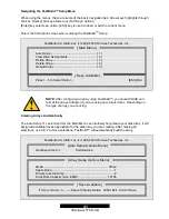
Page 23: ...y a Turn on or reboot your system b Press F2 to start BIOS setup utility BIOS Setup Utility Main Advanced Security Power Boot Exit Item Specific Help BIOS Version 1 00 xx Enable ACPI Enabled Installed OS Win2000 XP Reset Configuration Data Yes System Time 12 59 59 System Date 11 01 2002 NumLock Enabled System Information Tab Shift Tab or Enter selects field F1 Help Select Item Change Values F9 Set...

Page 24: ... default 3 2 BIOS Legend Bar The chart describes the legend keys and their alternates Key Function F1 or Alt H General help window ESC Exit current menu arrow keys Select a different menu or arrow keys Move cursor up down Tab or Shift Tab Cycle cursor up down Home or End Move cursor to top bottom of the window PgUp or PgDn Move cursor to next previous page F5 or Select the previous value setting o...

Page 25: ...No For operating systems that support the ACPI functionality Such as XP 2K and ME 3 3 2 Install OS Sub Menu Feature Option Description Install OS Other Win2000 XP Select the OS you will use most often 3 3 3 Reset Configuration Data Sub Menu Feature Option Description Reset Configuration Data Yes No This setting erases all configuration data in a section of memory for ESCD Extended System Configura...

Page 26: ...9 Setup Defaults ESC Exit Select Menu Enter Select Sub Menu F10 Save and Exit 3 4 1 Processors Sub Menu Feature Option Description Hyper Threading Enabled Disabled This setting determines whether the CPU Hyper Threading is activated 3 4 2 Chipset Sub Menu Feature Option Description Memory Remapping Enabled Disabled This setting determines whether the memory remapping is activated 3 4 3 Floppy Disk...

Page 27: ... is activated Option ROM Mode RAID Ultra ATA This setting determines what type of configuration you are using with the Promise chip 3 4 6 I O Device Configuration Sub Menu Feature Option Description Serial Port A Enabled Disabled Auto Enabled To turn on the port It requires entering a base I O address and an interrupt number Disabled To turn off the port Auto To configure the port automatically du...

Page 28: ... Feature Option Description Latency Timer Default 0020h 00E0h This setting controls how long each PCI device can hold the bus before another PCI device takes over When set to higher values every PCI device can conduct transactions for a longer time and thus improve the effective PCI bandwidth Graphic Aperture 256Mb 128Mb 64Mb 32Mb This setting controls system RAM allocation The aperture is a porti...

Page 29: ...Enter selects field F1 Help Select Item Change Values F9 Setup Defaults ESC Exit Select Menu Enter Select Sub Menu F10 Save and Exit 3 6 1 Remote Power On Sub Menu Feature Option Description Remote Power On Enabled Disabled Set to enable to have WOL wakeup on LAN support 3 6 2 After Power Failure Sub Menu Feature Option Description After Power Failure Stay Off Last State Power On This setting spec...

Page 30: ...ption Description Display Option ROM Message Enabled Disabled Set this option to enabled for allowing system to display PCI devices option ROMs during system boot up 3 7 3 Default Primary Video Adapter Sub Menu Feature Option Description Default Primary Video Adapter AGP PCI Set this option to control the system graphics device initialization priority Set to AGP To make the system initialize the A...

Page 31: ... boot All new selections you have made are stored into CMOS System will use the new settings to boot up 3 8 2 Exit Discarding Changes Use this option to exit setup utility and re boot All new selections you have made are not stored into CMOS System will use the old settings to boot up 3 8 3 Load Setup Defaults Use this option to load all default setup values Use this option when system CMOS values...

Page 32: ...ID 378 controller yet You MUST install the Windows NT4 2000 or XP driver software first onto this drive while it is still attached to your existing hard drive controller The PDC20378 controller supports up to two Serial ATA hard drives and two Parallel ATA hard drives 1 Configure the jumpers of the Parallel ATA hard drive you re preparing to connect to the SATA RAID controller using the proper Mas...

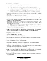
Page 33: ... PDC20378 and drives installed the Promise onboard BIOS will display the following screen FastTrak 378 tm BIOS Version 1 00 0 XX c 2002 2005 Promise Technology Inc All Rights Reserved No Array is defined Press Ctrl F to enter FastBuild tm Utility or Press ESC to continue booting 2 Press Ctrl F keys to display the FastBuild Utility Main Menu FastBuild tm Utility 2 xx c 2002 2005 Promise Technology ...

Page 34: ...ating your first array FastBuild tm Utility 2 xx c 2002 2005 Promise Technology Inc Optimize Array for Performance Mode Stripe Spare Drive 0 Drive s used in Array 2 Array Disk Capacity size in MB 16126 Up Down Space Change Option ESC Exit Ctrl Y Save Auto Setup Options Menu Array Setup Configuration Keys Available ...

Page 35: ...ng new hard drives follow these steps 1 Using the Spacebar choose Security under the Optimize Array for section 2 Press Ctrl Y keys to save your selection 3 The window below will appear Do you want the disk image to be duplicated to another Yes No Y Create and Duplicate N Create Only 4 Press N for the Create Only option 5 A window will appear almost immediately confirming that your Security array ...

Page 36: ... Channel ID Drive Model Capacity MB 1 Mas QUANTUMCR8 4A 8063 2 Mas QUANTUMCR8 4A 8063 Up Down ESC Exit Enter Select 4 Use the arrow keys to choose which drive contains the existing data to be copied 5 Press Enter key to save selection and start duplication The following progress screen will appear Start to duplicate the image Do you want to continue Yes No Y Continue N Abort 6 Select Y to continue...

Page 37: ... 2000 XP Setup screen press the Enter key Setup will now load all device files and then continue the Windows 2000 XP installation Existing Windows 2000 XP Installation After configuring the PDC20378 controller and rebooting your system Windows 2000 setup will show a Found New Hardware dialog box Under Windows 2000 XP the Mass Storage Controller will be displayed 1 Insert the PDC20378 RAID driver d...

Page 38: ... Driver diskette into the A drive 12 Press the Next button A message informing you that Windows 98 has found Win98 ME Promise FastTrak 378 or SATA 150 TX Series Controller should appear 13 Press Next then Finish then Yes when asked if you want to restart your computer Be sure to remove the diskette from drive A Existing Windows 98 Me Installation 1 After configuring the PDC20378 controller and the...

Page 39: ...d to specify any additional devices to be installed do so at this time Once all devices are specified continue to step 7 7 From the Windows NT Setup screen press the Enter key Setup will now load all device files and then continue the Windows NT installation 8 After a successful installation the SCSI Adapter Setup box will show that the Win NT Promise FastTrak 378 or SATA150 TX Series Controller d...

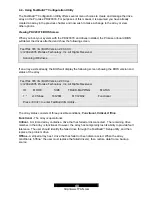
Page 40: ...llowing screen showing the BIOS version and status of the array FastTrak 378 tm BIOS Version 2 00 0 xx c 2002 2005 Promise Technology Inc All Rights Reserved ID MODE SIZE TRACK MAPPING STATUS 1 2 0 Stripe 16126M 611 128 32 Functional Press Ctrl F to enter FastBuild tm Utility The array status consists of three possible conditions Functional Critical Offline Functional The array is operational Crit...

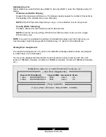
Page 41: ...sing FastBuild you should FDISK and format the arrayed drive s if you are using new blank drives Depending on the type of array you are using Creating Arrays Automatically The Auto Setup 1 selection from the Main Menu can intuitively help create your disk array It will assign all available drives appropriate for the disk array you are creating After making all selections use Ctrl Y to Save selecti...

Page 42: ...nly NOTE If you wish to customize the settings of individual disk arrays such as block size you must manually create disk arrays with the Define Array 3 option from the Main Menu Viewing Drive Assignments The View Drive Assignments 2 option in the Main Menu displays whether drives are assigned to a disk arrays or are unassigned The menu also displays the data transfer mode that relates to speed us...

Page 43: ...Stripe 2 16126 Functional Array 2 Array 3 Array 4 Up Down ESC Exit Del Delete 1 To delete an array highlight the Array you wish to delete and press the Del key 2 The View Array Definition menu will appear see below showing which drives are assigned to this array FastBuild tm Utility 2 xx c 2002 2005 Promise Technology Inc Array No RAID Mode Total Drv Capacity MB Status Array 1 Stripe Block 64 KB C...

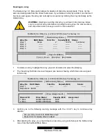
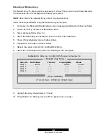
Page 44: ...u 3 Select submenu Define Array 3 4 Select the failed array and identify the Channel and ID of the failed drive 5 Power off and physically remove the failed drive 6 Replace the drive with an identical model 7 Reboot the system and enter the FastBuild Main Menu 8 Select the 5 Rebuild Array option The following screen will appear FastBuild tm Utility 2 xx c 2002 2005 Promise Technology Inc Array No ...

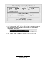
Page 45: ... Select Drive for Rebuild highlight the replacement drive 12 Press Enter and confirm that the data will be copied on to the selected drive All data on the replacement drive will be written over with mirrored information from the array drive A progress bar will appear as below Please Wait While Duplicating The Image 10 Complete 13 Once the rebuild process is complete the user will be asked to reboo...

Page 46: ...sk Do NOT copy CONFIG SYS and any Batch file bat to the disk 2 Download an updated BIOS Flash package from the Tyan web site http www tyan com 3 Unzip the BIOS Flash package and copy the unpacked files to the bootable floppy disk you created earlier you may need to copy the unpacked files to a separate clean floppy disk if there is not sufficient space in the bootable floppy disk Insure that there...

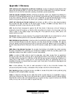
Page 47: ...list of all Initial Program Load IPL devices and then stores that list in NVRAM IPL devices have the ability to load and execute an OS as well as provide the ability to return to the BIOS if the OS load process fails At that point the next IPL device is called upon to attempt loading of the OS BIOS Basic Input Output System the program that resides in the ROM chip which provides the basic instruct...

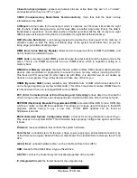
Page 48: ... frees up CPU resources for other tasks As with IRQs it is vital that you do not double up devices on a single line Plug n Play devices will take care of this for you DRAM Dynamic RAM widely available very affordable form of RAM which looses data if it is not recharged regularly every few milliseconds This refresh requirement makes DRAM three to ten times slower than non recharged RAM such as SRAM...

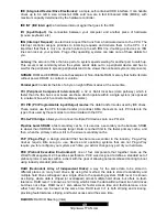
Page 49: ...es These modes use the CPU for data transfer in contrast DMA channels do not PCI refers to the type of bus used by these modes to communicate with the CPU PCI to PCI bridge allows you to connect multiple PCI devices onto one PCI slot Pipeline burst SRAM a fast secondary cache It is used as a secondary cache because SRAM is slower than SDRAM but usually larger Data is cached first to the faster pri...

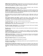
Page 50: ...es except the CPU shut down SDRAM Static RAM unlike DRAM this type of RAM does not need to be refreshed in order to prevent data loss Thus it is faster and more expensive SSI Server System Infrastructure a set of specifications covering common server hardware elements currently power supplies and electronics bays Standby mode in this mode the video and hard drives shut down all other devices conti...

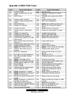
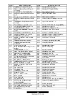
Page 51: ...ksum 58h 2 2 3 1 Test for unexpected interrupts 17h Initialize cache before memory autosize 59h Initialize POST display service 18h 8254 timer initialization 5Ah Display prompt Press F2 to enter SETUP 1Ah 8237 DMA controller initialization 5Bh Disable CPU cache 1Ch Reset Programmable Interrupt Controller 5Ch Test RAM between 512 and 640 KB 20h 1 3 1 1 Test DRAM refresh 60h Test extended memory 22h...

Page 52: ...lize local bus hard disk controllers D2h Unknown interrupt 92h Jump to UserPatch2 E0h Initialize the chipset 93h Build MPTABLE for multi processor boards E1h Initialize the bridge 95h Install CD ROM for boot E2h Initialize the CPU 96h Clear huge ES segment register E3h Initialize system timer 97h Fixup Multi Processor table E4h Initialize system I O 98h 1 2 Search for option ROMs E5h Check force r...

Page 53: ...t your dealer for help BEFORE calling TYAN 4 Check the TYAN user group alt comp periphs mainboard TYAN Returning Merchandise for Service During the warranty period contact your distributor or system vendor FIRST for any product problems This warranty only covers normal customer use and does not cover damages incurred during shipping or failure due to the alteration misuse abuse or improper mainten...

Page 54: ...on a circuit different from that of the receiver Consult the dealer on an experienced radio television technician for help Notice for Canada This apparatus complies with the Class B limits for radio interference as specified in the Canadian Department of Communications Radio Interference Regulations Cet appareil est conforme aux norms de Classe B d interference radio tel que specifie par le Minist...

Reviews: