background image

409-10092

Customer Manual

Crimp Quality Monitor 2031940-2 (For Use

1 of 86

LOC B

E2008 Tyco Electronics Corporation, Harrisburg, PA

All International Rights Reserved

TE logo and Tyco Electronics are trademarks.

*Trademark. Other products, logos, and company names used are the property of their respective owners.

TOOLING ASSISTANCE CENTER 1-800-722-1111

This controlled document is subject to change.

For latest revision and Regional Customer Service,

visit our website at www.tycoelectronics.com

08 SEP 08 Rev A

with AMPLIVAR* Product Terminator IIIA

Assembly 679453-[ ] and 679457-[ ])

READ THIS FIRST !

2

. . . . . . . . . . . . . . . . . . . . . . . . . .

SAFETY PRECAUTIONS

1. INTRODUCTION

3

. . . . . . . . . . . . . . . . . . . . . . . . . . . . . . . . . . . . . . . . . . . . . . . . . . .

1.1. The Crimp Quality Monitor

3

. . . . . . . . . . . . . . . . . . . . . . . . . . . . . . . . . . . . . . . .

1.2. The Manual

4

. . . . . . . . . . . . . . . . . . . . . . . . . . . . . . . . . . . . . . . . . . . . . . . . . . .

1.3. Specifications

4

. . . . . . . . . . . . . . . . . . . . . . . . . . . . . . . . . . . . . . . . . . . . . . . . .

2. RECEIVING, INSPECTION AND INSTALLATION

4

. . . . . . . . . . . . . . . . . . . . . . . . . . . .

2.1. Receiving

4

. . . . . . . . . . . . . . . . . . . . . . . . . . . . . . . . . . . . . . . . . . . . . . . . . . . .

2.2. Inspection

4

. . . . . . . . . . . . . . . . . . . . . . . . . . . . . . . . . . . . . . . . . . . . . . . . . . . .

2.3. Installation

5

. . . . . . . . . . . . . . . . . . . . . . . . . . . . . . . . . . . . . . . . . . . . . . . . . . . .

3. OPERATION

5

. . . . . . . . . . . . . . . . . . . . . . . . . . . . . . . . . . . . . . . . . . . . . . . . . . . . . .

3.1. Basic Outline of Operation

5

. . . . . . . . . . . . . . . . . . . . . . . . . . . . . . . . . . . . . . . .

3.2. Crimp Analysis Results

8

. . . . . . . . . . . . . . . . . . . . . . . . . . . . . . . . . . . . . . . . . . .

4. CRIMP QUALITY MONITOR MENUS AND SCREENS

10

. . . . . . . . . . . . . . . . . . . . . . .

4.1. Production

11

. . . . . . . . . . . . . . . . . . . . . . . . . . . . . . . . . . . . . . . . . . . . . . . . . .

4.2. Crimp Height Calibration

29

. . . . . . . . . . . . . . . . . . . . . . . . . . . . . . . . . . . . . . . . .

4.3. Job Setup

36

. . . . . . . . . . . . . . . . . . . . . . . . . . . . . . . . . . . . . . . . . . . . . . . . . . .

4.4. Kits

44

. . . . . . . . . . . . . . . . . . . . . . . . . . . . . . . . . . . . . . . . . . . . . . . . . . . . . . . .

4.5. Parts

50

. . . . . . . . . . . . . . . . . . . . . . . . . . . . . . . . . . . . . . . . . . . . . . . . . . . . . . .

4.6. System Settings Menu

61

. . . . . . . . . . . . . . . . . . . . . . . . . . . . . . . . . . . . . . . . . .

4.7. Statistics

77

. . . . . . . . . . . . . . . . . . . . . . . . . . . . . . . . . . . . . . . . . . . . . . . . . . .

4.8. Diagnostics Menu

78

. . . . . . . . . . . . . . . . . . . . . . . . . . . . . . . . . . . . . . . . . . . . .

4.9. Power Down

84

. . . . . . . . . . . . . . . . . . . . . . . . . . . . . . . . . . . . . . . . . . . . . . . . .

4.10. Version Screen

84

. . . . . . . . . . . . . . . . . . . . . . . . . . . . . . . . . . . . . . . . . . . . . . .

4.11. Enter Passsword Screen

85

. . . . . . . . . . . . . . . . . . . . . . . . . . . . . . . . . . . . . . . .

5. CRIMP QUALITY MONITOR MAINTENANCE

86

. . . . . . . . . . . . . . . . . . . . . . . . . . . . .

5.1. Touch Screen Cleaning

86

. . . . . . . . . . . . . . . . . . . . . . . . . . . . . . . . . . . . . . . . .

5.2. Daily Maintenance

86

. . . . . . . . . . . . . . . . . . . . . . . . . . . . . . . . . . . . . . . . . . . . .

5.3. Quality Control Maintenance

86

. . . . . . . . . . . . . . . . . . . . . . . . . . . . . . . . . . . . . .

5.4. Evaluation and Repair

86

. . . . . . . . . . . . . . . . . . . . . . . . . . . . . . . . . . . . . . . . . .

6. REVISION SUMMARY

86

. . . . . . . . . . . . . . . . . . . . . . . . . . . . . . . . . . . . . . . . . . . . . .

Summary of Contents for 2031940-2

Page 1: ...679457 READ THIS FIRST 2 SAFETY PRECAUTIONS 1 INTRODUCTION 3 1 1 The Crimp Quality Monitor 3 1 2 The Manual 4 1 3 Specifications 4 2 RECEIVING INSPECTION AND INSTALLATION 4 2 1 Receiving 4 2 2 Inspec...

Page 2: ...of the application equipment D NEVER insert hands into installed application equipment D NEVER alter modify or misuse the application equipment TOOLING ASSISTANCE CENTER CALL TOLL FREE 1 800 722 1111...

Page 3: ...1 The Crimp Quality Monitor Crimp Quality Monitor CQM 2031940 2 provides immediate inspection of the crimp height and the work curve of a crimped part wire terminal combination by analysis of data pr...

Page 4: ...ght 4 55 Kg 10 lbs ELECTRICAL REQUIREMENTS Voltage 100 240 Vac Frequency 50 60 AMBIENT OPERATING ENVIROMENT Temperature 5 40 C 41 104 F Relative Humidity 20 95 percent non condensing 2 RECEIVING INSPE...

Page 5: ...tach the I O Cable to the I O Port of the Crimp Quality Monitor 5 Attach the Sensor Cable to the Sensors Port of the Crimp Quality Monitor 6 Connect the power cord to the back of the Crimp Quality Mon...

Page 6: ...ls the monitor to automatically calculate the control limit tolerance for the part during production All other settings for the part are left at the default settings o Touch the button to save the cha...

Page 7: ...imp inspection and enter crimp height process is repeated h After the message Part has been calibrated is displayed touch the button to save the calibration values and return to the Crimp Height Calib...

Page 8: ...is within tolerance and the work index and peak force values are within the acceptable limits The green light is turned on and the CQM will advance to the next part in the kit See NOTE 3 below The ba...

Page 9: ...empt should be made to determine the cause when the crimp is determined to be Invalid For possible causes touch the button on the Invalid Crimp Data screen to display the Invalid Crimp Help screen Whe...

Page 10: ...tup screen Refer to Paragraph 4 3 Touch the Statistics button to display the Statistics screen Refer to Paragraph 4 7 Touch the Kits button to display the Kits screen Refer to Paragraph 4 4 Touch the...

Page 11: ...s These other screens are as follows S Learn Crimp Refer to Paragraph 4 1 L S Inspect Crimp Refer to Paragraph 4 1 M S Bad Crimp Height Refer to Paragraph 4 1 N S Control Count Error Refer to Paragrap...

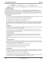
Page 12: ...he button to return to the Main Menu screen 4 1 A Kit Viewer Touching the Kit button on the Production screen will result in the Kit Viewer screen This screen displays parts in the kit currently selec...

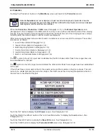
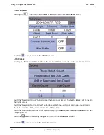
Page 13: ...ts screen Touch the Reset Batch Count button to reset the batch count to zero The batch statistics will be reset to their initial values Touch the Reset Batch and Job Count button to reset both the ba...

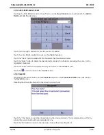
Page 14: ...n to delete the last character entered the character preceding the cursor or the highlighted characters Touch the Enter button to complete the entry and return to the Counts screen Touch the button to...

Page 15: ...luated by the CQM The Crimp Height Status Work Index Peak Force and Sample Count are displayed for this last part Touch the Crimp Height button to display the Crimp Height screen See Paragraph 4 1 G T...

Page 16: ...d nominal crimp height and tolerance for the part and the maximum and minimum values for the range of good crimp height values The calculated crimp height of the last crimp made is also displayed If t...

Page 17: ...imp Height screen to display the Force vs Position screen Refer to Paragraph 4 1 H The screens display the force and or position sensor data collected during the last crimp Touch the button to display...

Page 18: ...curs while the wire and terminal combination is being compressed The work index is a dimensionless value To establish the initial range for a good work index range values are collected from LEARN crim...

Page 19: ...tive value It has no specific units associated with it To establish the initial range for a good peak force range values are collected from LEARN crimps that are Accepted as good to create a peak forc...

Page 20: ...a new crimp height adjustment offset for the part to bring the sample crimp height within the control limit range However if the CQM is in the process of collecting data to calculate the control limi...

Page 21: ...button and the X button are shown when the crimp occurs while the Manual Operation screen is displayed The learn crimp counts for the job and the current batch will be incremented by one Touch the Cl...

Page 22: ...Operation screen 4 1 M Inspect Crimp The Inspect Crimp screen is displayed when the CQM calculates a crimp height that is within the specified crimp height tolerance for the part but the work index or...

Page 23: ...it sequence Because the kit will not contain all good parts the job and batch counts will not be incremented when the kit is completed Touch the Reset Kit button to return to the Production or Product...

Page 24: ...o the Production or Production CQM screen and reset to the first part in the kit The incomplete kit count will be incremented Touch the button to return to the Manual Operation screen 4 1 O Control Co...

Page 25: ...shown when the crimp occurs while the Manual Operation screen is displayed Touch the Repeat Crimp button to return to the Production or Production CQM screen and repeat the part in the kit sequence T...

Page 26: ...imp Status Help screen Touch the button to return to the Manual Operation screen 4 1 Q Batch and Job Complete The Batch Job Complete screen is displayed when the batch count is equal to the batch size...

Page 27: ...x peak force and sample count are displayed for the last part The CQM will not sequence through the parts in the kit The current part will not change until a new part is selected Touch the Crimp Heigh...

Page 28: ...on the Manual Operation screen will result in the Select Part to Run screen Touch the name of the part to be selected as the current part The name touched will be highlighted Touch the button to selec...

Page 29: ...The part s crimp height adjustment offset is set to a value that results in a crimp height that is within 0 127 millimeters 0 0005 inches of the part s nominal crimp height Also a position sensor valu...

Page 30: ...on and force data as the crimp is occurring After the crimp is complete the CQM analyzes the crimp data If the CQM is unable to complete its analysis of the data the Invalid Crimp Detected screen Para...

Page 31: ...y inspects the crimp to determine if the crimp can be used for calibration Touch the YES button to accept the crimp for calibration S If calibrating a kit and the crimp was for the last part in the ki...

Page 32: ...a crimp has occurred while the Calibrate Kit screen or Calibrate Part screen is displayed position and force sensor data is collected If the CQM determines that the data cannot be used for crimp heigh...

Page 33: ...ght adjustment offset A hand measured crimp height that would result in an adjust offset greater than 1 625 millimeters 0 064 inches may not be entered If the entered hand measured crimp height for al...

Page 34: ...occurring After the crimp is complete the CQM analyzes the crimp data If the CQM is unable to complete its analysis of the data the Invalid Crimp Detected screen Paragraph 4 2 C is displayed If the C...

Page 35: ...mp height that would result in an adjust offset greater than 1 625 millimeters 0 064 inches may not be entered If the entered hand measured crimp height is within 0 0127 millimeters 0 0005 inches of t...

Page 36: ...ch and job statistics are reset to their initial values Touch the Job Name button to display the Enter Job Name screen Refer to Paragraph 4 3 A Touch the Operator button to display the Operator screen...

Page 37: ...on period dash or the slash buttons to enter the job name Touch in the entry field to position the cursor or highlight characters Touch the Q A button to change to the optional button configuration To...

Page 38: ...an be created Touch the operator name to be selected or deleted from the list The name touched will be highlighted Touch the button to select the highlighted operator name and return to the Job Setup...

Page 39: ...n period button dash button or the slash button to enter the operator name Touch in the entry field to position the cursor or highlight characters Touch the Q A button to change to the optional button...

Page 40: ...poration 4 3 D Delete Operator Touching the button on the Operators screen will result in the Delete Operator screen Touch the Yes button to delete the operator name and return to the Operators screen...

Page 41: ...the button to display the Enter New Kit Name screen Refer to Paragraph 4 4 A Touch the button to display the Kit Editor screen to in order to edit the highlighted kit Refer to Paragraph 4 4 B Touch t...

Page 42: ...or equal to the batch size Touch the 0 through 9 buttons to enter the job size Touch the entry field to position the cursor or highlight characters Touch the Clear button to delete all the characters...

Page 43: ...than or equal to the job size Touch the 0 through 9 buttons to enter the batch size Touch the entry field to position the cursor or highlight characters Touch the Clear button to delete all the chara...

Page 44: ...isplay the Enter New Kit Name screen Refer to Paragraph 4 4 A Touch the button to display the Kit Editor screen to edit the highlighted part Refer to Paragraph 4 4 B Touch the button to display the En...

Page 45: ...button or the semicolon button to enter the new kit name Touch the entry field to position the cursor or highlight characters Touch the Q A button to select the optional button configuration Touch the...

Page 46: ...l be highlighted Touch the button to add another part to the kit and display the Part Select For Kit screen See Paragraph 4 4 C Touch the button to edit the highlighted part and display the Part Edito...

Page 47: ...display the Enter New Part Name screen Refer to Paragraph 4 5 A Touch the button to display the Part Editor screen to in order to edit the highlighted part Refer to Paragraph 4 5 B Touch the button t...

Page 48: ...e dash button the slash button or the semicolon button to enter the new kit name Touch the entry field to position the cursor or highlight characters Touch the Q A button to select the optional button...

Page 49: ...it Touching the button on the Kits screen will result in the Delete Kit screen Touch the Yes button to delete the kit name and return to the Kits screen Only the kit name is deleted The part names use...

Page 50: ...n Refer to Paragraph 4 5 A Touch the button to display the Part Editor screen to edit the highlighted part Refer to Paragraph 4 5 B Touch the button to display the Enter New Part Name For Copy screen...

Page 51: ...button or the semicolon button to enter the new part name Touch the entry field to position the cursor or highlight characters Touch the Q A button to select the optional button configuration Touch t...

Page 52: ...utton to display the Enter Peak Force Coefficient screen Refer to Paragraph 4 5 G Touch the Work Index button to display the Enter Work Coefficient screen Refer to Paragraph 4 5 H Touch the Calculate...

Page 53: ...ction The minimum value that may be entered is 0 000 mm 0 000 inches The maximum value that may be entered is 3 556 mm 0 1400 inches Touch the 0 through 9 buttons and the decimal button to enter the c...

Page 54: ...ished good range it is identified as a BAD crimp The minimum value that may be entered is 0 000 mm 0 000 inches The maximum value that may be entered is 0 251 mm 0 0099 inches Touch the 0 through 9 bu...

Page 55: ...ayed Refer to Paragraph 4 1 M The minimum value that may be entered is 0 000 mm 0 000 inches The maximum value that may be entered is 0 251 mm 0 0099 inches The control limit is divided by the square...

Page 56: ...he nominal crimp height for the part from the maximum crimp height for the part The maximum crimp height for the part can be found on the tooling matrix in the customer manual for the APT IIIA machine...

Page 57: ...cceptable peak force values is determined the range is recalculated after every GOOD crimp The peak force value of the GOOD crimp is used to calculate a new average value and standard deviation for th...

Page 58: ...able work index values is determined the range is recalculated after every GOOD crimp The work index value of the GOOD crimp is used to calculate a new average value and standard deviation for the wor...

Page 59: ...e dash button the slash button or the semicolon button to enter the new part name Touch the entry field to position the cursor or highlight characters Touch the Q A button to select the optional butto...

Page 60: ...ctronics Corporation 4 5 J Delete Part Touching the button on the Parts screen will result in the Delete Part screen Touch the Yes button to delete the part name and return to the Parts screen Touch t...

Page 61: ...the display backlight is turned off and the screen will turn black The display will turn back on when the next crimp or touch occurs Touch the Process Control button to display the Process Control sc...

Page 62: ...Size screen Refer to Paragraph 4 6 B Touch the Learn Count button to display the Enter Learn Count screen Refer to Paragraph 4 6 C Touch the Control Count button to display the Enter Control Count sc...

Page 63: ...he control limit of the part divided by the square root of the sample size The minimum value for the sample size is 1 The maximum value for the sample size is 99 Touch the 0 through 9 buttons to enter...

Page 64: ...methods The minimum value for the learn count is 3 The maximum value for the learn count is 99 Touch the 0 through 9 buttons to enter the learn count Touch the entry field to position the cursor or h...

Page 65: ...he Control Count Error screen is displayed The minimum value for the control count is 1 The maximum value for the control count is 99 Touch the 0 through 9 buttons to enter the control count Touch the...

Page 66: ...nguage Units Touching the Language Units button on the System Settings Menu screen will result in the Language Units screen The language selection specifies what language is used for the screens The u...

Page 67: ...display a list of language choices Touch the desired language from the list Touch the current units selection to display a list of unit choices Touch the desired units from the list Touch the button t...

Page 68: ...in the fixture used to collect the output data to derive the six coefficients and the CQM s A D converter This procedure must be performed when the CQM is initially configured for use An error messag...

Page 69: ...s to enter the zero 0 order coefficient Touch the entry field to position the cursor or highlight characters Touch the Clear button to delete all the characters that have been entered Touch the Back b...

Page 70: ...first character if the coefficient is negative Touch the 0 through 9 buttons to enter the first order coefficient Touch the entry field to position the cursor or highlight characters Touch the Clear b...

Page 71: ...e is plugged into one of the USB ports on the back of the Crimp Quality Monitor Touch the Backup Parts Kits button to display the Enter Database Backup Filename screen Refer to Paragraph 4 6 J Touch t...

Page 72: ...micolon in the file name Add the TGZ extension to the file name Touch the 0 through 9 buttons the A through Z buttons or the dash button to enter the file name Touch the entry field to position the cu...

Page 73: ...reen This screen is used to restore kit part and system settings data from a backup file Touch the Select File button to display the Select Filename to Restore Database screen Use this screen to selec...

Page 74: ...button on the USB screen will result in the Select Firmware File screen This screen allows the user to download the latest version of the CQM software from a USB drive to the CQM Touch the file name t...

Page 75: ...en a character is entered it is displayed as an asterisk Touch the entry field to position the cursor or highlight characters Touch the Q A button to select the optional button configuration Touch the...

Page 76: ...the Software Setup screen The Crimp Quality Monitor can be used on a variety of terminating machines When used on the APT IIIA machine the software setup selection must be set to APTCQM for proper op...

Page 77: ...ing the Statistics button on the Main Menu screen will result in the Statistics screen The Statistics screen is used to view current job and batch statistics Touch the button to send the statistics to...

Page 78: ...he Sensors screen Refer to Paragraph 4 8 A Touch the Adjust Motor button to display the Adjust Motor screen Refer to Paragraph 4 8 B Touch the Inputs Outputs button to display the Inputs Outputs scree...

Page 79: ...86 Tyco Electronics Corporation 4 8 A Sensors Touching the Sensors button on the Diagnostics Menu screen will result in the Sensors screen Touch the button to display the CQM Sensors Help screen Touc...

Page 80: ...crimp height adjust motor in order to increase the crimp height Touch the button to move the crimp height adjust motor in order to decrease the crimp height Touch the button to perform the adjustment...

Page 81: ...on on the Diagnostics Menu will result in the Inputs Outputs screen The symbol indicates the input output is off The symbol indicates the input output is on Touch buttons 1 through 6 to toggle the cor...

Page 82: ...onics Corporation 4 8 D Printer Test Touching the Printer button on the Diagnostics Menu screen will result in the Printer Test screen Touch the Test button to send data to the printer connected to th...

Page 83: ...sage screen is displayed during operation of the CQM If the CPU temperature exceeds 80 C the system board temperature exceeds 55 C or the system temperature exceeds 55 C a warning message is displayed...

Page 84: ...er and the Restart button are displayed The CQM can now be turned off without loosing production information Touch the button to return to the Main Menu screen 4 10 Version Screen Touching the title b...

Page 85: ...t password by doing the following 1 Make the current Job Name 22253667 2 Make the current Operator 72779673 3 Select System Settings from the Main Menu screen and enter 892 on the Enter Password scree...

Page 86: ...oth DO NOT use objects that could damage the CQM 2 Make sure all components are in place and properly secured 3 Always leave the CQM turned off for a minimum of 10 seconds before reapplying power so t...

Reviews: