
Instruction Sheet
AMP NETCONNECT*
MRJ21* 24-Port 10/100/1000BASE-T
408-8974
LOC B
1 of 2
E2007 Tyco Electronics Corporation, Harrisburg, PA
All International Rights Reserved
TE logo and Tyco Electronics are trademarks.
*Trademark. Other products, logos, and company names used are the property of their respective owners.
TOOLING ASSISTANCE CENTER1-800-722-1111
PRODUCT INFORMATION 1-800-522-6752
This controlled document is subject to change.
For latest revision and Regional Customer Service,
visit our website at www.tycoelectronics.com
19 JUN 08 Rev D
Straight Patch Panels 1777029-[ ]
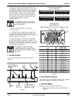
Figure 1
AMP NETCONNECT* AMPTRAC*
Printed Circuit (PC) Board Subassembly
(Patch Panel -2 Only)
Front of Patch Panel
Back of Patch Panel
HDP-22 Connector
(Patch Panel -2 Only)
MRJ21 Receptacle
(4 Places)
Port Identification
(24 Places)
Port Identification
(4 Places)
16 RJ45 Connector
Assembly (4 Places)
AMPTRAC Port Identification
(Patch Panel -2 Only)
Blank Label Pad
(24 Places)
EIA Rack
(Ref)
12-24 Screw
(4 Places)
1. INTRODUCTION
MRJ21 24–Port 10/100/1000BASE–T Straight Patch
Panels 1777029–[ ] are designed to be mounted onto
a standard 483–mm [19–in.] Electronic Industries
Alliance (EIA) rack or equipment cabinet as shown in
Figure 1. Patch Panel –2 is designed for use with the
AMP NETCONNECT AMPTRAC system. Read these
instructions thoroughly before starting installation.
All numerical values in this instruction sheet are
in metric units [with U.S. customary units in
brackets]. Dimensions are in millimeters [and
inches]. Figures are not drawn to scale.
For Patch Panel -2, these instructions assume
that the reader understands the operation of
equipment and software used with the
AMPTRAC system.
AMPTRAC Retrofit Kit 1479894–1 can be installed
onto Patch Panel –1 to enable the patch panel to be
connected to the AMP NETCONNECT AMPTRAC
system. Back Cable Manager Kits 1933352–[ ] or
Wiring Distribution Bracket Kit 557548–1 must be
used to support the cable.
To obtain information on AMP NETCONNECT
products, call PRODUCT INFORMATION at the
number at the bottom of this page, or visit the
AMP NETCONNECT website at
www.ampnetconnect.com.
Reasons for reissue of this instruction sheet are
provided in Section 6, REVISION SUMMARY.
2. DESCRIPTION
Each patch panel contains four MRJ21 receptacles
(one per 1
6 RJ45 connector assembly). The ports
are identified by numbers printed on the front and on
the back of the patch panel,
and blank label pads are
provided on the front for identifying connecting ports.
Four 12–24 screws are included to mount the patch
panel to the rack.
In addition, Patch Panel –2 has a pc board
subassembly and HDP–22 connector to enable the
patch panel to connect to the AMP NETCONNECT
AMPTRAC system.
3. INSTALLATION
1. Using the screws, mount the patch panel onto
the rack. Refer to Figure 1.
NOTE
i
NOTE
i


