background image

5

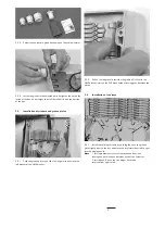
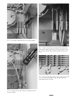
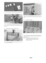
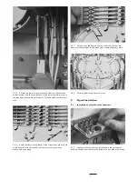
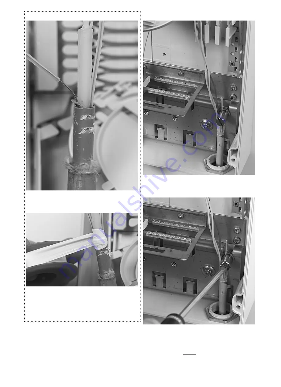
4.2.1 Pull the cable back in the correct position, the cable jacket
should protrude 30 mm into the box. passing the cable strapping point.   

4.2

Cable termination

For slotted core cable only

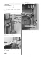
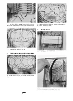
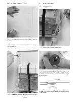
4.1.3.1 Install a protection tube of 150 mm over the fibers of each slot
and slide it into the slot of the cable.

4.1.3.2 Protect the transition from the cable to the tubes with a few
layers of Teflon tape.

4.1.3.3 Consider the protection tubes now as loose tubes in the
installation.

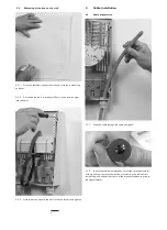
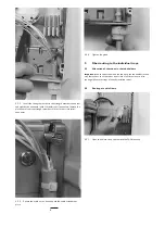
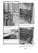
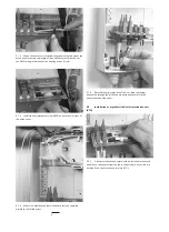
4.2.2 Insert the strength member in the strength member connector
and tighten the connector with a screwdriver. If necessary remove the
plastic core from the straight member till it fits in the strain relief
connector. 

Summary of Contents for Raychem FIST-MB2-S

Page 1: ...Closing the box 8 Important steps 9 Rearrangements Contents 1 Introduction 1 1 Product Description The FIST MB2 S is a Generic Box for a fiber management system that offers the function of splicing c...

Page 2: ...strap FAS cap including the Tray wedge Cable strain relief connectors and fixing plate Cable glands Tiewraps The Cover including 4 preinstalled screws Installation instruction 3 Installation 3 1 Prep...

Page 3: ...p with the tray and move the tray lateral from left to right into the hinging cavity Note 1 for single element tray start on the second position leaving one position open between each of the cassettes...

Page 4: ...iameter does not match with the diameter of the gland seal remove the plastic nut metal ring and rubber seal inside the gland and peel out some of the break out rubber rings up to the right diameter 3...

Page 5: ...over the fibers of each slot and slide the tube into the slot of the cable 4 1 3 2 Protect the transition from the cable to the tubes with a few layers of Teflon tape 4 1 3 3 Consider the protection...

Page 6: ...in case of re routing without crossings of already installed tubes 5 2 Routing of cable fibers 4 2 2 Insert the strength member in the strength member connector and tighten the connector with a screwd...

Page 7: ...he loose tubes in the tubeholder and slide the tube holder retainer with the snap forwards in the lowest possible cavity of the tube holder above the loose tubes The tube holder retainer must snap 5 2...

Page 8: ...y on the fibers in the tray and make sure that the fibers are well contained in FAS block and wraparound groove plate 6 Fiber organisation on trays after splicing 6 1 Take the splice protector and put...

Page 9: ...thout creating crossings and without creating distortions on the tubes already installed in the tube holder Use correct lengths in the tubeholder Make sure not to loose ID 9 Rearrangement Avoid to pul...

Page 10: ...10...

Page 11: ...11...

Page 12: ...no warranties as to its accuracy or completeness and disclaims any liability in connection with its use Tyco Electronics obligations shall only be as set forth in Tyco Electronics Standard Terms and...

Page 13: ...the pigtail seals 6 Fiber organisation after splicing 7 Closing the box 8 Important steps 9 Rearrangements Contents 1 Introduction 1 1 Product Description The FIST MB2 T is a Generic Box for a fiber...

Page 14: ...g pin and retainers Velcro strap FAS cap including the tray wedge Cable strain relief connectors and fixing plate patch panel with 2 anti movements strips AMS Cable glands including pigtail seals 4 pi...

Page 15: ...bon 4 8 trays the tray hinges have to be inserted from right to left 3 2 3 Install the glands in the selected ports by tighten the nut on the inside of the box do not forget to install the rubber ring...

Page 16: ...the box on the wall 3 5 3 Hold the base part onto the wall Insert the screws and tighten 4 1 2 In case the cable diameter does not match with the diameter of the gland seal remove the plastic nut meta...

Page 17: ...bers of each slot and slide it into the slot of the cable 4 1 3 2 Protect the transition from the cable to the tubes with a few layers of Teflon tape 4 1 3 3 Consider the protection tubes now as loose...

Page 18: ...fibers 4 3 1 Allocation of the tubes in the tube holders Important loose tubes should be routed up to the tube holder in such way that access to all the tubes is possible at all times in case of re ro...

Page 19: ...ube holder above the loose tube s The tube holder retainer must snap 4 3 8 Store the fibers temporarily on a tray 5 Pigtail installation 5 1 Installation of pigtails with connectors 4 3 6 Route the fi...

Page 20: ...d and mount the connectors to the adapter on the patch panel 5 2 Installation of pigtails with Kevlar termination unit KTU 5 1 3 Install the anti movement strip AMS on both the slot sides of the patch...

Page 21: ...for 2000 mm through the patch panel and mark them 5 2 6 Take the two pigtails and bend the Kevlar over the inner part lips back between the two parts of the KTU Mark the pigtails 50 mm away from the c...

Page 22: ...ers in the rubber wrap around seal of the pigtail seal 5 4 Installation of pigtail gland seals 5 3 1 Guide the fibers to the cassette through the groove under the tray hinge 5 4 2 Position the rubber...

Page 23: ...older 7 1 Install the FAS block cap and the retainer 7 Closing the box 6 Fiber organisation on trays after splicing 6 2 Different types of splice holders can be fitted in the tray with the use of an a...

Page 24: ...insert first the four guiding pins in the box before installing the cover Raychem NV Telecom Outside Plant Diestsesteenweg 692 B 3010 Kessel Lo Belgium Tel 32 16 351 011 Fax 32 16 351 697 www tycoele...

Reviews: