signed to NFPA 13D or NFPA 13R
are given in Table A as a function of
temperature rating and the maximum
allowable coverage areas. The single
sprinkler flow rate is the minimum re-
quired discharge from the most hy-
draulically demanding single sprin-
kler and, the multiple sprinkler flow
rate is the minimum required dis-
charge from each of the total
number of “design sprinklers” as
specified in NFPA 13D or NFPA 13R.
TIA 99-1 (Tentative Interim Amend-
ment) with an effective date of May
22, 2000 states that the minimum re-
quired discharge from each of the
“design sprinklers” for systems de-
signed to NFPA 13 must be calcu-
lated based on delivering a minimum
design density of 0.1 gpm/sq. ft. for
each of the listed coverage areas
shown in Table A. Consult with the
Authority Having Jurisdiction regard-
ing the application of this TIA to the
currently adopted NFPA 13.
For systems designed to NFPA 13,
13D, or 13R, consult with the local
authority having jurisdiction with re-
gard to the number of “design sprin-
klers” for sloped ceilings having a
slope greater than a 2 inch rise for a
12 inch run.
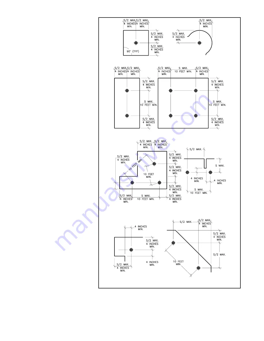
Spray Coverage Criteria.
Figure 2
and 3 provide spacing rules that
must be followed to assure that the
Model TFP1 Sprinklers will provide
their design distribution of water
spray.
Location of sprinklers with respect to
obstructions to water distribution are
to be in accordance with the obstruc-
tion rules for extended coverage pen-
dent sprinklers per the requirements
of NFPA 13.
Operational Sensitivity Criteria.
For proper operational sensitivity,
the Model TFP1 must be installed be-
neath a solid ceiling having a
smooth or textured surface.
The Model TFP1 must
NOT
be used
above or below open-gridded type
suspended ceilings; beneath soffits
or beams exceeding 3 inches in
height; or, with beams, joists, or
ducts having a height of more than 3
inches located within the sprinkler
coverage areas. Beams having a
height of more than 3 inches may be
located with their centerlines along
the boundaries separating adjacent
sprinkler coverage areas.
Cold Soldering Criteria.
Figures 2
and 3 provide the minimum spacing
requirements necessary for prevent-
ing the wetting (i.e., cold soldering)
of the heat responsive element of a
non-operated Model TFP1, which is
adjacent to one which has operated.
Heat Source Criteria.
Refer to
Figure 2-1 (Plan View)
Figure 2-2 (Plan View)
Figure 2-3 (Plan View)
Figure 2-4 (Plan View)
Figure 2-5 (Plan View)
Figure 2-6 (Plan View)
Figure 2-7 (Plan View)
Figure 2-8 (Plan View)
Figure 2
Spacing Rules Under Level Ceilings
S
=
THE LENGTH OF THE COVERAGE AREA BEING
HYDRAULICALLY CALCULATED (REF. TABLE A).
3
OBSOLETE


