


INSTALLATION
The 8.0 K-Factor, SuperNova S126 Sprinklers must be in-
stalled in accordance with the following instructions:
NOTES
A leak tight 3/4 inch NPT sprinkler joint should be ob-
tained with a torque of 10 to 20 ft.lbs. (13,6 to 27,1 Nm).
A maximum of 30 ft.lbs. (40,7 Nm) of torque is to be used
to install sprinklers. Higher levels of torque may distort
the sprinkler inlet with consequent leakage or impairment
of the sprinkler.
Do not attempt to compensate for insufficient adjustment
in an Escutcheon Plate by under- or over-tightening the
Sprinkler. Readjust the position of the sprinkler fitting to
suit.
1. The S126 Sprinklers must be installed with their center-
line of waterway parallel to the ceiling and perpendicular
to the back wall surface. The word “TOP” on the deflec-
tor must face upwards toward the ceiling.
2. After installing an escutcheon (as applicable) over the
sprinkler pipe threads and with pipe thread sealant ap-
plied to the pipe threads, hand tighten the sprinkler into
the sprinkler fitting.
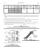
3. Wrench tighten the Sprinkler using only the W-Type 11
Sprinkler Wrench (Ref. Figure 2). The wrench recess of
the W-Type 11 is to be applied to the sprinkler wrench-
ing area (Ref. Figure 1).
STAR SPRINKLER
Page 2
1-2.3.21
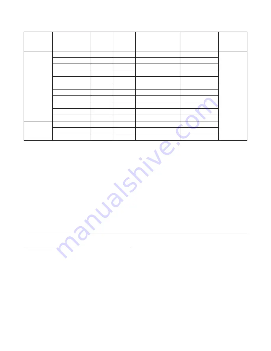
TABLE A
UL AND ULC LISTING CRITERIA FOR INSTALLATION OF
8.0 K-FACTOR, SUPERNOVA S126 (SIN S1868) QR-EC HORIZONTAL SIDEWALL SPRINKLERS
Application
Coverage Area
W x L
FT. x FT. (m x m)
Minimum
Flow
(c)
GPM (LPM)
Minimum
Pressure
(c)
PSI (BAR)
Sprinkler
Temperature Rating
°F
16 x 16 (4,9 x 4,9)
140, 165
26 (98)
10.6 (0,73)
38 (144)
22.6 (1,56)
QR-EC
(a)
16 x 18 (4,9 x 5,5)
16 x 18 (4,9 x 5,5)
13.1 (0,90)
29 (110)
NOTES:
(a) For use in QR-EC and EC Light Hazard Occupancy automatic sprinkler system applications per NFPA 13.
(b) For use in EC Light Hazard Occupancy automatic sprinkler system applications per NFPA 13.
(c) Requirement is based on minimum flow in GPM from each sprinkler. The indicated residual pressures are based on the nominal K-factor.
(d) The centerline of the sprinkler waterway (Ref. Figure 1) is located 7/16 inch (11,1 mm) below the deflector (Ref. Figure 1).
(e) Follow the requirements of NFPA 13 for spacing of the S126 Sprinklers with respect to ceiling mounted obstructions.
(f) The minimum allowable spacing along a wall between the S126 Sprinklers, to prevent cold soldering, is 10 feet (3,1 m).
(g) The maximum permitted ceiling slope per NFPA 13 is a 2 inch (50,8 mm) rise over a 12 inch (304,8 mm) horizontal run, with ceiling
sloping downwards from the wall on which the sprinkler is located.
Deflector
To Ceiling
Distance(
d)
Inches (mm)
4 to 6 (100 to 150)
Deflector Boss
To Wall
Distance
(e)
Inches (mm)
2 to 6
(50 to 150)
16 x 20 (4,9 x 6,1)
16 x 20 (4,9 x 6,1)
14 x 22 (4,3 x 6,7)
16 x 22 (4,9 x 6,7)
16 x 24 (4,9 x 7,3)
18 x 16 (5,5 x 4,9)
18 x 18 (5,5 x 5,5)
20 x 16 (6,1 x 4,9)
16 x 20 (4,9 x 6,1)
16 x 22 (4,9 x 6,7)
16 x 24 (4,9 x 7,3)
EC
(b)
34 (129)
45 (170)
37 (140)
37 (140)
44 (167)
31 (117)
33 (125)
35 (133)
45 (170)
37 (140)
44 (167)
18.1 (1,25)
31.6 (2,18)
21.4 (1,48)
21.4 (1,48)
30.3 (2,09)
15.0 (1,03)
17.0 (1,17)
19.1 (1,32)
31.6 (2,18)
21.4 (1,48)
30.3 (2,09)
4 to 6 (100 to 150)
4 to 18 (100 to 450)
4 to 6 (100 to 150)
4 to 18 (100 to 450)
4 to 6 (100 to 150)
4 to 6 (100 to 150)
4 to 6 (100 to 150)
4 to 6 (100 to 150)
4 to 6 (100 to 150)
4 to 6 (100 to 150)
4 to 18 (100 to 450)
4 to 6 (100 to 150)
4 to 6 (100 to 150)
140, 165
140, 165
140, 165
140
140, 165
140
140
140, 165
140, 165
140, 165
165
165
165
OBSOLETE


