

TFP800
Page 2 of 6
Design
Criteria
Nozzle Placement
Where direct impingement of water
spray onto all of the protected surface
is required by the authority having juris-
diction, the nozzles are to be spaced
and directed so that their spray pat-
terns will completely cover the plane-
of-protection with the minimum
required average density. However, it
is recommended that indoor nozzle
spacing be 12 ft (3,7 m) or less and that
outdoor nozzle spacing be 10 ft (3,0 m)
or less. Where rundown or slippage is
planned, for example, exposure protec-
tion of vessels per NFPA 15, the above
recommended indoor and outdoor
spacings also apply.
When used for protecting the surfaces
of a vessel, for example, the nozzles
are positioned normal to and approx-
imately 2 ft (0,6 m) from the surface.
This approach, in conjunction with
a properly selected spray angle, will
tend to make more effective use of the
spray as well as help minimize the dis-
turbance effects of wind/draft condi-
tions on the water spray patterns.
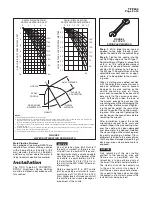
Spray Patterns
The Design Spray Profiles for the nozzle
spray angles of 65 to 180 degrees are
shown in Figure 2 and apply to dis-
charge pressures of 20 to 60 psi (1,4
to 4,1 bar). Discharge pressures in
excess of 60 psi (4,1 bar) will result in a
decrease in coverage area because the
spray patterns tend to draw inwards
at higher pressures. Refer inquiries
on higher discharge pressures to the
Technical Services Department.
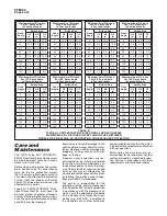
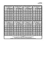
The maximum axial distances between
the nozzle tip and plane-of-protection,
for exposure protection, are given in
Table E and F. When the axial distance
from the nozzle tip to the plane-of-
protection is 2 ft (0,6 m) or less, the
Design Spray Profile is the same as
the nominal spray angles of 65 to 140
degrees.
Heat Sensitivity
Because the Type EA-1 PROTEC-
TOSPRAY Directional Spray Nozzles
are automatic nozzles, they must be
located with consideration of their
ability to detect abnormal tempera-
ture increases due to fire. Therefore,
it is recommended that NFPA 13 be
reviewed with respect to the rules
that define the permitted distance
below ceilings and the spacing limita-
tions for standard coverage automatic
sprinklers as a function of occupancy
hazard.
ORIFICE
SIZE
Inches
MINIMUM
DIAMETER
Inches (mm)
K-FACTOR
GPM/psi
½
LPM/bar
½
1/4
0.220 (5,59)
1.4
20,2
3/8
0.312 (7,92)
2.8
40,3
1/2
0.435 (11,05)
5.6
80,6
65°
95°
80°
110°
125°
140°
160°
180°
TEMPERATURE
RATING
FRAME
COLOR
CODE
BULB
CODE
COLOR
LIQUID
135°F (57°C)
Unpainted
Orange
175°F (79°C)
White
Yellow
250°F (121°C)
Blue
Blue
325°F (163°C)
Red
Mauve
400°F (204°C)
Green
Black
500°F (260°C)
Orange
Black
FINISH &
MATERIAL
TEMPERATURE
RATINGS
Natural Finish
Bronze
All Ratings
Chrome Plated
Bronze
135°F (57°C)
175°F (79°C)
250°F (121°C)
325°F (163°C)
Lead Coated
Bronze
Corrosion-Resistant
Wax-Coated Bronze
135°F (57°C)
175°F (79°C)
STAMPED ON
WRENCHING
AREA FOR
1/4" & 3/8"
-
2
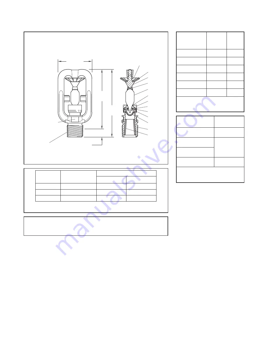
Deflector
Pin
Lower Bulb Seat
Upper Bulb Seat
-
5
4 -
3 -
Components:
Frame
1 -
NOMINAL MAKE-IN
7/16" (11,1 mm)
3-7/16"
(87,3 mm)
(76,2 mm)
3"
1-3/4"
(44,5 mm)
ORIFICE
SIZE
2
5
3
11
9
4
7
8
6
10
1
12
6
Button
-
7
Spacer
-
8
Spring Plates
-
9
Gasket
Lower Bulb
-
Gasket
10 -
11 Bulb
-
12 Bushing
-
(1/4" & 3/8"
orifice only)
1/2"
NPT
MARKING
SPRAY ANGLE
FIGURE 1
TYPE EA-1 PROTECTOSPRAY NOZZLE
NOMINAL DIMENSIONS
TABLE A
SELECTION OF ORIFICE SIZES
TABLE B
SELECTION OF SPRAY ANGLES
TABLE C
SELECTION OF
TEMPERATURE RATINGS
TABLE D
SELECTION OF
FINISH AND MATERIALS


