

TFP800
Page 3 of 6
Main Pipeline Strainers
Main pipeline strainers per NFPA 15 are
required for systems utilizing nozzles
with a flow path less than 3/8 in. (9,5
mm) diameter, that is, K=1.4 (Table A),
and for any system where the water is
likely to contain obstructive material.
Installation
The TYCO Type EA-1 PROTECTO-
SPRAY Directional Spray Nozzles
must be installed in accordance with
this section.
NOTICE
Do not install an Type EA-1 Nozzle if
the bulb is cracked or there is a loss
of liquid from the bulb. With the sprin-
kler held horizontally, a small air bubble
should be present. The diameter of the
air bubble is approximately 3/32 in.
(2,4 mm) for the 135°F (57°C) to 1/4 in.
(6,4 mm) for the 500°F (260°C) temper-
ature ratings.
Obtain a leak-tight 1/2 in. NPT nozzle
joint by applying a minimum-to-maxi-
mum torque of 7 to 14 ft-lb (9,5 to 19,0
N
∙
m). Higher levels of torque can distort
the nozzle inlet and cause leakage or
impairment of the nozzle.
Step 1.
With pipe-thread sealant
applied to the pipe threads, hand-
tighten the nozzle into the nozzle fitting.
Step 2.
Tighten the nozzle into the
nozzle fitting using only the W-Type 11
Sprinkler Wrench (Figure 3), except that
an 8 in. or 10 in. adjustable crescent
wrench is to be used for wax-coated
nozzles. With reference to Figure 1,
the W-Type 11 Sprinkler Wrench or the
adjustable crescent wrench, as appli-
cable, is to be applied to the wrench-
ing area.
When installing wax-coated nozzles
with the adjustable crescent wrench,
exercise additional care to prevent
damage to the wax coating on the
nozzle wrenching area or frame
arms and, consequently, exposure of
bare metal to the corrosive environ-
ment. Sufficiently widen the jaws of
the wrench enough to pass over the
wrenching area without damaging the
wax coating. Before wrench-tighten-
ing the nozzle, adjust the jaws of the
wrench to contact the nozzle wrench-
ing area. After wrench-tightening the
nozzle, loosen the wrench jaws before
removing the wrench.
After installation, inspect the nozzle
wrenching area and frame arms and
retouch (repair) the wax coating wher-
ever the coating has been damaged
and bare metal is exposed. Retouch
the wax coating on the wrenching area
by gently applying a heated 1/8 in.
diameter steel rod to the areas of wax
that have been damaged, smoothing it
back over areas where bare metal is
exposed.
NOTICE
Only retouching of the wax coating
applied to the wrenching area and
frame arms is permitted, and the
retouching is to be performed only at
the time of the initial nozzle installation.
The steel rod should be heated only
to the point at which it can begin to
melt the wax, and appropriate precau-
tions need to be taken when handling
the heated rod in order to prevent the
installer from being burned.
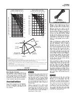
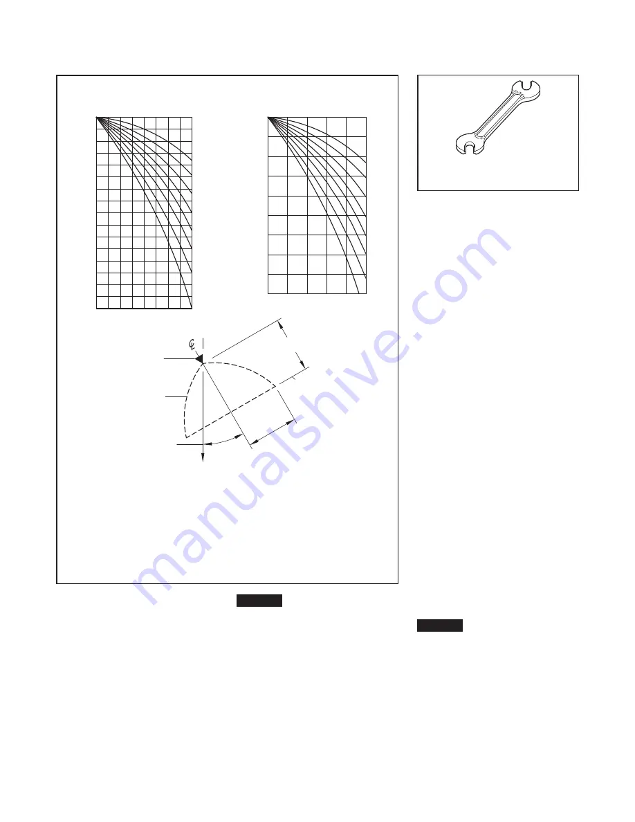
NOTES:
1. Design data obtained from tests in still air.
2. Design data applies to a residual (flowing) pressure range at the nozzle inlet of 20 to 60 psi (1,4 to 4,1 bar). For
pressures up to 175 psi (12,1 bar) consult Johnson Controls Technical Services.
Refer to the authority having jurisdiction for their minimum required residual pressures.
3. The shapes of the Design Spray Profiles remain essentially unchanged over the maximum Axial Distances shown
in Tables E and F.
4. For axial distances of 2 feet (0,6 meters) and less and for nozzle spray angles of 65° to 140°, the Design Spray
Profile is the same as the nominal spray angle.
5. The maximum Axial Distances shown in Tables E and F are based on exposure protection.
95°
65°
80°
110°
125°
140°
160°
180°
0
16
14
12
10
8
6
4
2
0
2
4
6
8
RADIAL DISTANCE FROM
NOZZLE CENTERLINE, FEET
AXIAL DIST
ANCE FROM NOZZLE, FEET
125°
140°
160°
95°
80°
110°
65°
180°
AXIAL DIST
ANCE FROM NOZZLE, METRES
RADIAL DISTANCE FROM
NOZZLE CENTERLINE, METERS
2,5
2,0
1,5
1,0
0,5
0
4,5
4,0
3,5
3,0
2,5
2,0
1,5
1,0
0
0,5
RADIAL
DISTANCE
GRAVITY
FIXED ANGLE
SPRAY
PROFILE
(ORIENTATION)
PROTECTION
PLANE OF
NOZZLE
AXIAL DISTANCE
FIGURE 2
WATER DISTRIBUTION DESIGN DATA
FIGURE 3
W-TYPE 11
SPRINKLER WRENCH


