TFP852
Page 6 of 6
1400 Pennbrook Parkway, Lansdale, PA 19446 | Tel1-215-362-0700
© 2020 Johnson Controls. All rights reserved. All specifications and other information shown were current as of document revision date and are subject to change without notice.
Limited
Warranty
For warranty terms and conditions, visit
www.tyco-fire.com.
Ordering
Procedure
Contact your local distributor for avail-
ability. When placing an order, indicate
the full product name and part number
(P/N).
Model TN-17 Horizontal
Spray Nozzle
Specify: Model TN-17 Horizontal Spray
Nozzle, K=16.8, (specify) Thread Con-
nection, P/N (specify):
ISO 7-R 3/4. . . . . . . . . . . . . . . . . . . 49-017-2-001
3/4 in. NPT . . . . . . . . . . . . . . . . . . . 49-017-2-002
ISO 7-R 3/4 w/ Dust Cap . . . . . . . . 49-017-3-001
3/4 in. NPT w/ Dust Cap . . . . . . . .49-017-3-002
Sprinkler Wrench
(separately ordered)
Specify: W-Type 21 Sprinkler Wrench,
P/N 56-001-0-686
Care and
Maintenance
The TYCO Model TN-17 K=16.8 Hori-
zontal Spray Nozzle must be main-
tained and serviced in accordance with
this section.
Before closing a fire protection system
main control valve for maintenance
work on the fire protection system that
it controls, permission to shut down the
affected fire protection system must be
obtained from the proper authorities
and notify all personnel who may be
affected by this action.
Nozzles which are exhibiting visible
signs of corrosion must be replaced.
Care must be exercised to avoid
damage to the nozzles before, during,
and after installation. Nozzles damaged
by dropping, striking, wrench twist/slip-
page, or the like, must be replaced. See
the Installation section for additional
information.
The Tunnel Operator is responsi-
ble for the inspection, testing, and
maintenance of their fire protection
system and devices in compliance
with this document, in addition to the
standards of any authorities having
jurisdiction. Contact the installing con-
tractor or product manufacturer with
any questions.
Fire protection systems are recom-
mended to be inspected, tested, and
maintained by a qualified Inspec-
tion Service in accordance with local
requirements and/or national codes.
Installation
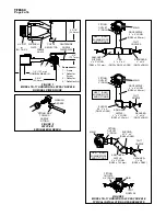
The TYCO Model TN-17 K=16.8 Hori-
zontal Spray Nozzle, as shown in
Figures 1 and 2, must be installed in
accordance with this section.
NOTICE
The Model TN-17 Nozzle must be
installed in accordance with the pipe
dimensions shown in Figure 3. Failure
to do so will impair the intended perfor-
mance of the system.
General Instructions
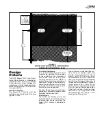
The Model TN-17 Nozzle is to be ori-
ented horizontally with the plane
created by its two frame arms paral-
lel with the ceiling or parallel with the
finished grade, in the case of a non-flat
ceiling.
Step 1.
Ensure all piping components
are properly assembled as shown in
Figure 3 prior to installing the Model
TN-17 Nozzle.
Step 2.
With pipe-thread sealant
applied to the nozzle threads, hand-
tighten the Model TN-17 Nozzle into
the Reducer.
Step 3.
The Model TN-17 Nozzle must
be tightened using only the W-Type 21
Sprinkler Wrench as shown in Figure 2.
Fully engage the nozzle wrench flats as
shown in Figure 1 and wrench tighten.
A leak-tight 3/4 in. NPT or ISO 7-R
3/4 sprinkler joint should be obtained
by applying a minimum-to-maximum
torque of 20 to 30 ft-lb (26,8 to 40,2
N
∙
m). Higher levels of torque can
distort the nozzle inlet with consequent
leakage or impairment of the nozzle.
Ensure the markings on the deflector
face towards the ceiling.


