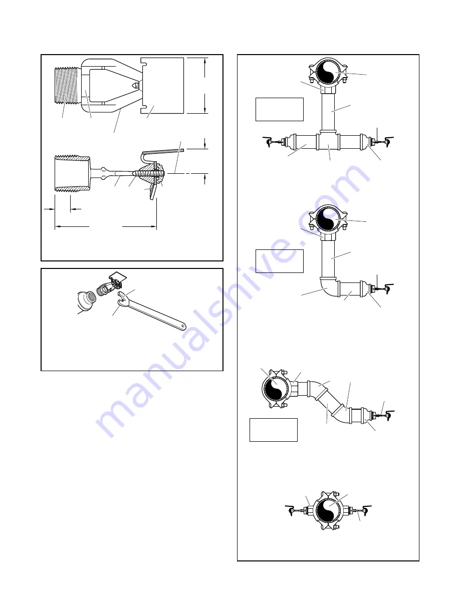
background image

TFP850

Page 2 of 6

3

4

1
2

-
-

-
- Deflector

Deflector

Deflector Nut

Frame

Screw

Components:

WRENCH

FLATS

FRAME

ARMS

3-3/4"

(95,3 mm)

2-1/16"

(52,4 mm)

TOP OF

DEFLECTOR

CENTERLINE

NOZZLE

WATERWAY

1" NPT

or

ISO 7-R 1

7/8"

(22,2 mm)

1

2

3

4

 9/16"(14,3 mm)

NOMINAL MAKE-IN

TN-25

NOZZLES

TN-25

NOZZLES

TN-25

NOZZLE

TN-25

NOZZLE

REDUCERS:

2" x 1"

(DN50 x DN25)

REDUCER:

2" x 1"

(DN50 x DN25)

REDUCER:

2" x 1"

(DN50 x DN25)

ARM-OVER

NIPPLE:

2" x 5" LONG

(DN50 x 125 mm)

ARM-OVER

NIPPLE:

2" x 5" LONG

(DN50 x 125 mm)

ARM-OVER

NIPPLES:

2" x 5" LONG

(DN50 x 125 mm)

DROP NIPPLE:

2" x 8" LONG

(DN50 x 200 mm)

DROP NIPPLE:

2" x 8" LONG

(DN50 x 200 mm)

TEE:

2" x 2" x 2"

(DN50 x DN50 x DN50)

FITTING

OUTLET

2" (DN50)

FITTING

OUTLET

2" (DN50)

FITTING

OUTLET

2" (DN50)

FITTING

OUTLETS

1" (DN25)

MAIN

MAIN

MAIN

MAIN

USE 1" (DN25)

MINIMUM PIPE

AND FITTINGS

USE 1" (DN25)

MINIMUM PIPE

AND FITTINGS

USE 1" (DN25)

MINIMUM PIPE

AND FITTINGS

ELBOW:

90° 2" x 2"

(DN50 x DN50)

ELBOWS:

45° 2" x 2"

(DN50 x DN50)

WRENCH

RECESS

"FITTING SIDE"

TOWARD

NOZZLE

FITTING

FIGURE 1 

MODEL TN-25 HORIZONTAL SPRAY NOZZLE 

NOMINAL DIMENSIONS

FIGURE 3 

MODEL TN-25 HORIZONTAL SPRAY NOZZLE 

TYPICAL INSTALLATION ARRANGEMENTS

FIGURE 2 

W-TYPE 1 

SPRINKLER WRENCH

Summary of Contents for TN-25

Page 1: ...ers who thoroughly understand the limitations as well as capabilities of such systems The Tunnel Operator is responsible for maintaining their fire protection system and devices in proper operating con dition Contact the installing contrac tor or product manufacturer with any questions General Description The TYCO Model TN 25 Horizontal Spray Nozzle having a 25 2 K360 K factor is a specialized ope...

Page 2: ... 125 mm ARM OVER NIPPLES 2 x 5 LONG DN50 x 125 mm DROP NIPPLE 2 x 8 LONG DN50 x 200 mm DROP NIPPLE 2 x 8 LONG DN50 x 200 mm TEE 2 x 2 x 2 DN50 x DN50 x DN50 FITTING OUTLET 2 DN50 FITTING OUTLET 2 DN50 FITTING OUTLET 2 DN50 FITTING OUTLETS 1 DN25 MAIN MAIN MAIN MAIN USE 1 DN25 MINIMUM PIPE AND FITTINGS USE 1 DN25 MINIMUM PIPE AND FITTINGS USE 1 DN25 MINIMUM PIPE AND FITTINGS ELBOW 90 2 x 2 DN50 x D...

Page 3: ...in the application environment Obstructions The maximum allowable vertical and horizontal distance that the bottom of an obstruction can be away from the Model TN 25 Nozzle is provided in Graph A Non continuous suspended obstruc tions such as air handlers lights and the like are to meet the 4x rule of Figure 6 within 5 ft 152 4 cm of the nozzle deflector in the area below the nozzle the obstructio...

Page 4: ...LE DISTANCE FROM NOZZLE ft SPRAY PROFILES 18 ft BELOW NOZZLE UL testing measured at 18 ft below nozzle Spray Profile Pressure PSI Distance from Nozzle ft 19 7 A 24 10 B 27 15 C 30 20 D 34 25 E 36 5 30 F B F A C D E 1 2 3 4 5 6 7 1 2 3 4 5 6 7 8 9 10 11 12 13 14 16 DISTANCE BELOW NOZZLE m NOZZLE DISTANCE FROM NOZZLE m SPRAY PROFILES 5 5 m BELOW NOZZLE UL testing measured at 5 5 m below nozzle Spray...

Page 5: ...OWED IN AREA ABOVE AND BELOW NOZZLE DEFLECTOR AS DEFINED ON ELEVATION VIEW 3 0 CENTERLINE OF NOZZLE 1 NOTES PLACE LARGE OBSTRUCTIONS SIGNS ETC PARALLEL TO NOZZLE DISCHARGE IN AREAS BETWEEN NOZZLES 4 MAXIMUM LATERAL DISTANCE FROM CENTERLINE OF NOZZLE TO OBSTRUCTION FEET METERS DISTANCE FROM END OF DEFLECTOR TO OBSTRUCTION FEET METERS DISTANCE FROM END OF DEFLECTOR TO OBSTRUCTION FEET METERS 0 OBSTR...

Page 6: ...5 Nozzle into the Reducer Step 3 The Model TN 25 Nozzle must be tightened using only the W Type 1 Sprinkler Wrench as shown in Figure 2 Fully engage the nozzle wrench flats as shown in Figure 1 and wrench tighten A leak tight 1 in NPT or ISO 7 R 1 sprin kler joint should be obtained by apply ing a minimum to maximum torque of 20 to 30 ft lb 26 8 to 40 2 N m Higher levels of torque can distort the ...

Reviews: