background image

TFP850

Page 3 of 6

Design 

Criteria

The TYCO Model TN-25 K=25.2 Hor-

izontal Spray Nozzle is intended for 

integration into a water spray, deluge 

fire protection system designed in 

accordance with the applicable stan-

dards recognized by any authorities 

having jurisdiction.

Nozzle Orientation

The Model TN-25 Nozzle must be 

installed in a horizontal orientation. 

See Figures 1 and 3.

Corrosion Resistance

It is recommended that the Tunnel 

Operator be consulted with respect 

to the suitability of the materials of 

construction and finish for any given 

corrosive environment. The effects of 

ambient temperature, concentration of 

chemicals, and gas/chemical velocity, 

should be considered, at a minimum, 

along with the corrosive nature to which 

the nozzles may be exposed.
The pipe, fittings, hangers, and hanger 

components must be suitable for use in 

the application environment.

Obstructions

The maximum allowable vertical and 

horizontal distance that the bottom of 

an obstruction can be away from the 

Model TN-25 Nozzle is provided in 

Graph A.
Non-continuous suspended obstruc-

tions such as air handlers, lights, and 

the like are to meet the “4x rule” of 

Figure 6; within 5 ft (152,4 cm) of the 

nozzle deflector in the area below the 

nozzle, the obstruction must be located 

four (4) times the longest dimension of 

the obstruction as defined in Figure 

6, to a maximum of 60 in. (152,4 cm). 

No obstructions are allowed to be 

located within the designated shaded 

region. Care must be taken to place 

large obstructions running parallel to 

the nozzle discharge, such as signs, in 

the areas between the nozzles.
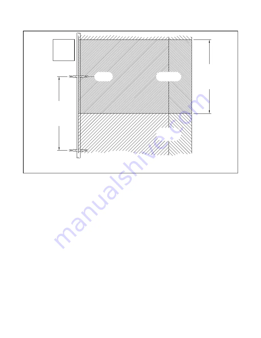
TN-25

NOZZLE

NOZZLES

AND

FITTINGS

SHOWN

ENLARGED

COVERAGE

AREAS

ADJACENT

COVERAGE

AREAS

7 psi (0,5 bar)

14'-0" (4,3 m)

-or-

10 to 30 psi

(0,7 to 2,1 bar)

16'-4" (5,0 m)

7 psi (0,5 bar)

14'-0" (4,3 m)

-or-

10 to 30 psi

(0,7 to 2,1 bar)

16'-4" (5,0 m)

FIGURE 4 

MODEL TN-25 HORIZONTAL SPRAY NOZZLE 

COVERAGE AND SPACING – PLAN

Summary of Contents for TN-25

Page 1: ...ers who thoroughly understand the limitations as well as capabilities of such systems The Tunnel Operator is responsible for maintaining their fire protection system and devices in proper operating con dition Contact the installing contrac tor or product manufacturer with any questions General Description The TYCO Model TN 25 Horizontal Spray Nozzle having a 25 2 K360 K factor is a specialized ope...

Page 2: ... 125 mm ARM OVER NIPPLES 2 x 5 LONG DN50 x 125 mm DROP NIPPLE 2 x 8 LONG DN50 x 200 mm DROP NIPPLE 2 x 8 LONG DN50 x 200 mm TEE 2 x 2 x 2 DN50 x DN50 x DN50 FITTING OUTLET 2 DN50 FITTING OUTLET 2 DN50 FITTING OUTLET 2 DN50 FITTING OUTLETS 1 DN25 MAIN MAIN MAIN MAIN USE 1 DN25 MINIMUM PIPE AND FITTINGS USE 1 DN25 MINIMUM PIPE AND FITTINGS USE 1 DN25 MINIMUM PIPE AND FITTINGS ELBOW 90 2 x 2 DN50 x D...

Page 3: ...in the application environment Obstructions The maximum allowable vertical and horizontal distance that the bottom of an obstruction can be away from the Model TN 25 Nozzle is provided in Graph A Non continuous suspended obstruc tions such as air handlers lights and the like are to meet the 4x rule of Figure 6 within 5 ft 152 4 cm of the nozzle deflector in the area below the nozzle the obstructio...

Page 4: ...LE DISTANCE FROM NOZZLE ft SPRAY PROFILES 18 ft BELOW NOZZLE UL testing measured at 18 ft below nozzle Spray Profile Pressure PSI Distance from Nozzle ft 19 7 A 24 10 B 27 15 C 30 20 D 34 25 E 36 5 30 F B F A C D E 1 2 3 4 5 6 7 1 2 3 4 5 6 7 8 9 10 11 12 13 14 16 DISTANCE BELOW NOZZLE m NOZZLE DISTANCE FROM NOZZLE m SPRAY PROFILES 5 5 m BELOW NOZZLE UL testing measured at 5 5 m below nozzle Spray...

Page 5: ...OWED IN AREA ABOVE AND BELOW NOZZLE DEFLECTOR AS DEFINED ON ELEVATION VIEW 3 0 CENTERLINE OF NOZZLE 1 NOTES PLACE LARGE OBSTRUCTIONS SIGNS ETC PARALLEL TO NOZZLE DISCHARGE IN AREAS BETWEEN NOZZLES 4 MAXIMUM LATERAL DISTANCE FROM CENTERLINE OF NOZZLE TO OBSTRUCTION FEET METERS DISTANCE FROM END OF DEFLECTOR TO OBSTRUCTION FEET METERS DISTANCE FROM END OF DEFLECTOR TO OBSTRUCTION FEET METERS 0 OBSTR...

Page 6: ...5 Nozzle into the Reducer Step 3 The Model TN 25 Nozzle must be tightened using only the W Type 1 Sprinkler Wrench as shown in Figure 2 Fully engage the nozzle wrench flats as shown in Figure 1 and wrench tighten A leak tight 1 in NPT or ISO 7 R 1 sprin kler joint should be obtained by apply ing a minimum to maximum torque of 20 to 30 ft lb 26 8 to 40 2 N m Higher levels of torque can distort the ...

Reviews: