background image


12/2010 

KASTOR OY


TYLÖ MEGA – LINE SUPER 10 

Sivu 10/22

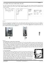
5.2. External Signal Light 

The signal light may be connected to connectors 5 and 6. It must be noted that the light does not indicate the state of the timer 
switch, but only whether the heating coils are active. 
 

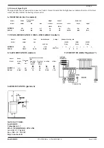
6. TECHNICAL DATA (table 2) 


Heater 

Heater 

Sauna room 
volume 


Weight 

Amount 


Heater size 


Model 

output 

Min 

Max 

without 

of stones 

width 

depth 

height 


stones 

(Max) 


SUPER 10 

kW 

m3 

m3 

kg 

kg 

Mm 

mm 

mm 

DI 10 K 

10,00 

8,0 

15,0 

16 

22 

Ø

 370 

450 

590 


7. FUSES, RESISTANCE COILS AND CABLES (table 3) 


Heater 

Heater 

Fuse 

Installation size 

Voltage 

Number of heating coils  


Model 

output 

size 


1600W 

1700W 

2000W 


400 V 3N~ 


Group 

Group 

Group 

SUPER 10 

kW 

mm2 

DI 10 K 

10,00 

3x16 

5x2,5  

400V 3N~ 

   2 2 2        


8. SAFE DISTANCES (table 4)  


9. CIRCUIT DIAGRAM (picture 7) 


SAFE DISTANCES (picture 6) 


MANUFACTURER: 
KASTOR OY 
Tehtaankatu 5 – 7 
FIN-11710 RIIHIMÄKI, FINLAND 
tel. +358 - 19 – 764 360 
Fax. +358 - 19 – 721 883 
http://www.kastor.fi


Heater 

Sauna 

Safe distances for heater 


(Min) 

Model 

From side 

height 

From front  From front 

to ceiling 

to floor 

to 


(Min) 

wall 

to upper 

to lower 


bench 

bench 


SUPER 10 

mm 

mm 

mm 

mm 

mm 

mm 

DI 10 K 

2100 

100 

70 

30 

1350 

110 


Summary of Contents for MEGA-LINE SUPER 10

Page 1: ...he upper plate of the back casing Use the lower rim of the inner casing with support from the upper part instead A free corridor should be left at one side of the heater for maintenance work 2 3 Connection to The Power Grid The heater s electrical installation must be performed by a certified electrician Check the heater s technical data prior to connection The connection to the power grid may onl...

Page 2: ...rew underneath the control panel 2 Move the rubber gaskets on the decorative piping further away from the control panel 3 Remove the control panel by pulling it outwards from the piping the plastic material used tolerates bending well 4 The keyboard connector cable in the connection room has some slack to allow pulling the control panel further from the piping 5 Detach the cable at the keyboard s ...

Page 3: ... used for any other purpose The sauna room must be checked before the heater is switched on Beware the hot heater as its stones and metal parts may scald your skin at operating temperatures Care is mandated in the heater s vicinity as well particularly due to the danger of slipping During water throwing you should watch the hot drops spraying from the stones and the hot steam Parents must watch sm...

Page 4: ...manner Press TIME Type in your desired preset time 1 10 hours Press ON The preset time is activated and the signal light blinks at the chosen hour setting Once the heating current has engaged after the preset time has run out the heater will run for three hours and then cut off automatically You may also turn off the heat prior to that by pressing OFF If you want to continue bathing past those thr...

Page 5: ...0 450 590 7 FUSES RESISTANCE COILS AND CABLES table 3 Heater Heater Fuse Installation size Voltage Number of heating coils Model output size 1600W 1700W 2000W 400 V 3N Group Group Group SUPER 10 kW A mm2 V 1 2 3 1 2 3 1 2 3 DI 10 K 10 00 3x16 5x2 5 400V 3N 2 2 2 8 SAFE DISTANCES table 4 9 CIRCUIT DIAGRAM picture 7 SAFE DISTANCES picture 6 MANUFACTURER KASTOR OY Tehtaankatu 5 7 FIN 11710 RIIHIMÄKI ...

Reviews: