7
Unusual voltages/numbers of phases
Contact Tylö Customer Service before connecting to voltages or
numbers of phases that are not listed in the wiring diagram Figure
18.
External ON/OFF switch (option)
The external ON/OFF switch can be positioned anywhere outside
the sauna, not to exceed 75 feet from the heater, to avoid voltage
loss in the cable. Voltage loss aff ects the LED indicator for heater
status (if built-in and connected to the switch).
For further information, see instructions supplied with the control
panel.
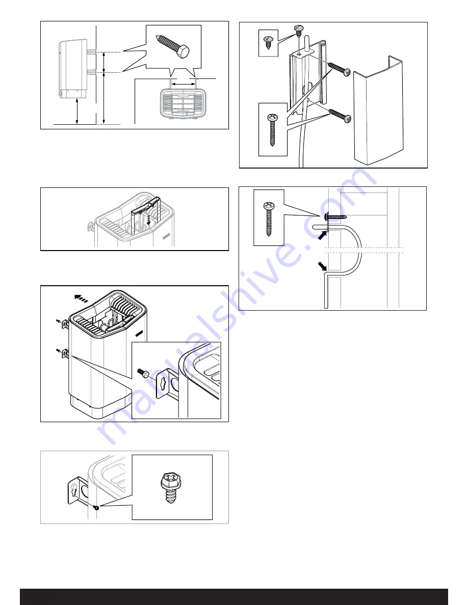
Figure 13: Fitting the fragrance holder/air humidi
fi
er
11.
Hang the heater on the screws see Fig. 14.
Figure 14: Hang the heater up.
12.
Lock the heater into place with the lock screw see Fig. 15.
Figure 15: Lock screw for bracket
13.
Install the sensor on the wall see Fig 16. The thermistor wire
may also be passed through the wall. Seal any holes in the
wall behind the sensor, see Figure 17. The thermistor wire
may be extended outside the sauna using low voltage wire
(2-lead).
Figure 12: Dimensioning
1. 10.31 in
2. 6 in
3. 16.3 in
4. 8.11 in
10.
Fit herb bowl/air humidifi er (see Fig. 13).
2
4
3
1
Figure 16: Installing the sensor
Figure 17: Seal any holes


