4. Stopping the engine and the Tractor
(1) Decrease the throttle opening and depress clutch pedal. When necessary, depress also the brake
pedal, thus halting the tractor.
(2) Put the shifting levers to the neutral position, release the clutch pedal and lock the brake pedal if
necessary.
(3) Idling the engine for something until the water temperature drops to below 70
°
C, then pulling the
shut-off pull rod to stop the engine. It is strictly forbidden to stop the engine suddenly from high
temperature.
26
gear
1st
2nd
3rd
4th
5th
6th
7th
8th
Rotary tillage,
Transplantation
Plowing, harrowing and seeding
Transportation
Usage
Harvesting
Table 4-1 Usage of various speeds of tractor
4.3 Operation of the Working facilities
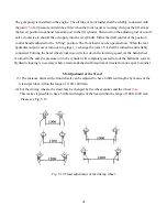
1. Operation and Control of the PTO Shaft (see
Fig.4-3
)
(1) Put the control lever of the PTO shaft at neutral position. Remove the PTO shaft guard and connect
reliably the PTO shaft to the implement.
(2) Depress the clutch pedal. Depending on the requirement of the implement the control lever of the
PTO shaft is set at the high or low position
(3) Gradually release the clutch pedal to start the implement. First run the implement at low speed to
inspect the the operation condition. If it runs normally, it will be put to work in the normal condition.
2. The Operation and Control of the Hydraulic Lift System (see Fig 5-12, 5-13)
(1) The main technical specifications of hydraulic lift system
Type : Partial separated units
Working depth control :Position control, draft and position combined control, float control
Type of pumping :CB310(right-handed)(ET 350 ECONO)
CB310(left-handed)(ET 350 ECONO)
Displacement of oil pump(mL/r) :10;14
Change over valve :Two-position, Y-way sliding type
Summary of Contents for ET350 ECONO
Page 69: ...62 8 3 Electrical system wiring diagram...
Page 73: ...66 ET 350 ECONO 4WD TRACTOR ENGINE PARTS CATALOGUE...
Page 74: ...67 1 INTAKE AND EXHAUST PIPE ASSEMBLY...
Page 76: ...69 2 CYLINDER HEAD ASSEMBLY...
Page 80: ...73 3 CYLINDER BLOCK ASSEMBLY...
Page 84: ...77 4 CAMSHAFT ASSEMBLY...
Page 86: ...79 5 CRANKSHAFT FLYWHEELASSEMBLY...
Page 88: ...81 6 PISTON CONNECTING ROD ASSEMBLY...
Page 90: ...83 7 FUEL SYSTEM ASSEMBLY...
Page 92: ...85 8 COOLING SYSTEM...
Page 95: ...88 9 LUBRICATION SYSTEM ASSY...
Page 97: ...90...
Page 98: ...91 Electric EGR Illustration Diagram...
Page 100: ...93 ET 350 ECONO 4WD TRACTOR Chassis PARTS CATALOGUE...
Page 102: ...95 1 DRY AIR FILTER...
Page 104: ...97 2 ENGINE CONTROL MECHANISM ASSY...
Page 107: ...100 3 CLUTCH...
Page 110: ...103 4 INTERMEDIATE HOSE ASSY...
Page 113: ...106 5 TRANSMISSION HOUSING...
Page 116: ...6 PRIMARY SHAFT 109...
Page 118: ...7 MAIN SHAFT 111...
Page 120: ...8 TRANSMISSION COVER ASSY 113...
Page 122: ...9 DIFFERENTIAL 115...
Page 124: ...10 PTO SHAFT ASSY 117...
Page 126: ...11 BRAKE ASSY 119...
Page 129: ...122 12 REAR DRIVING WHEEL ASSY...
Page 131: ...124 13 FINAL DRIVE ASSY...
Page 134: ...14 FUEL TANK BRACKET 127...
Page 136: ...15 SUSPENSION LINKAGE ASSY 129...
Page 139: ...16 FRONT DRIVING AXLE ASSY A 132...
Page 142: ...17 FRONT DRIVING AXLE ASSY B 135...
Page 145: ...138 18 FRONT DRIVING AXLE ASSY C...
Page 147: ...140 19 FRONT DRIVING AXLE ASSY D...
Page 150: ...143 20 FRONT DRIVING WHEELASSY...
Page 152: ...145 21 STEERING MECHANISM...
Page 154: ...147 22 TRANSFER CASE ASSY...
Page 157: ...150 23 HYDRAULIC POWER LIFT...
Page 160: ...153 24 POWER LIFT CONTROL MECHANISM...
Page 163: ...156 25 CYLINDER DISTRIBUTOR ASSY...
Page 166: ...159 26 FENDER FLOOR BOARD TOOL BOX...
Page 168: ...161 27 BONNET 1...
Page 171: ...164 28 BONNET 2...
Page 173: ...166 29 SIDE COVER...
Page 175: ...ET350 ECONO OPERATOR S MANUAL FOR TRACTORS CODE NO Printed on June 2006 2 nd EDITION...


