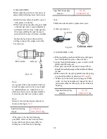
7) Sub change counter shaft
8) Differential gears.
Note:
1.Apply grease when installing Needle bearing.
2.After installation, be sure to slide smoothly.
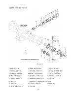
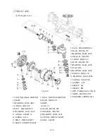
1.C-RING , SHAFT
2.GEAR , SPUR 21T
19.BEARING , BALL/HL1
(6206)
20.GEAR , SPUR 19-28T
21.BEARING , NEEDLE.
ROLLER (KT252913)
22.GEAR , SPUR 28T
23.WASHER , 20X34X3
24.BEARING,
BALL/HL1(6304)
13.C-RING , HOLE 14.SHIM , 0.5 (3)
15.SHIM , 0.2 (4) 16.SHIM , 0.1 (3)
17.DIFF ASSY , RR
18.PINION , DRIVE 9T
19.GEAR , BEVEL 55T 20.CASE , DIFF
21.PINION , DIFF 12T
29 28 25 26 19
27
25
22 21 24 23
20 31 30
13
14 15 16
32 33
34 35
Fig.5-53
Note:
1.When assembling without replacing the pinion gear and ring gear with new ones, provide the
same shimming thickness as that provided before disassembly.
2.Backlash between diff-pinion and diff-side gear should be within as range of 0.1 to 0.2mm
(0.004-0.008 in) and these parts should turn smoothly.
3.When reassembling the used pinion and ring gear, reinstall the same thickness of shims as was
installed before disassembly in each shimming position.
4.Backlash adjustment between the drive pinion and the ring pair(Fig5-34).As the drive pinion
and the ring gear make a pair,be sure not to mate them with other parts from differential
tractors.
5.Adjust the shimming to backlash of 0.1-0.2 mm (0.004-0.008 in). The standard shimming is
2.6mm (0.102 in
) on right side and
1.1mm (0.043in)
on left side.
5-32
21.PINION , DIFF 12T
22.COLLAR , PINION THRUST
23.SHAFT , DIFF PINION 24.PIN , SPRING
25.WASHER, THRUST 34X46X1
26.GEAR , BEVEL RH 20T
27.GEAR , BEVEL LH 20T
28.CLUTCH COMP , DIFF LOCK
29.BEARING , BALL 30.BOLT , HEX/S
31.BEARING , BALL
32.SHIM , 0.2 (8) 33.SHIM , 0.1 (6)
34.METAL , DIFF CASE
35.BOLT , HEX/S
Fig.5-54
20 31 30
18
Summary of Contents for T233 HST
Page 14: ...1 11...
Page 15: ...1 12...
Page 22: ...SECTION 3 GEAR TRAIN DIAGRAMS FIG 1 3 GEAR TRAIN DIAGRAM 1 19...
Page 33: ...SECTION 2 OPERATION CHART FOR DISASSEMBLY AND REASSEMBLY BY MAJOR BLOCKS 2 4...
Page 60: ...3 HST main pump case 4 5...
Page 64: ...6 Hydrostatic system schematic 4 8...
Page 100: ...3 Rear transmission case 5 15 Fig 5 23...
Page 121: ...Power Train Diagram Fig 5 60 5 36...
Page 210: ...SECTION 6 WIRING DIAGRAM 10 12...


