SECTION 7. TROUBLESHOOTING
Important: Whenever effecting a repair the reason for the cause of the problem must be investigated
and corrected to avoid repeating failure.
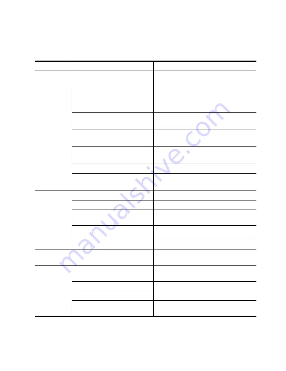
The following table lists problems and their possible causes with the recommended remedial action
1. LIGHTING SYSTEM
Problems
Causes
Countermeasures
Several or all
lights do not
illuminate
Discharged battery
Check battery and charge or renew
Loose or defective battery cable
connection
Inspect,clean,and tighten connection
Loose wire harness connectors
Check and ensure connectors securely
engaged
Burnt out fuse or fusible link
Inspect and renew.Check circuit before re-
connecting power
Faulty wiring
Check lighting Circuit wiring and repair or
renew
Defective light switch
Check and renew
Several light bulbs burnt out due
to defective voltage regulation
Check and renew voltage regulator
(Alternator)
10-15
to defective voltage regulation
(Alternator)
Individual
lights do not
illuminate
Burnt out bulb
Check and renew
Defective or corroded bulb contact
Inspect,clean or renew
Burnt out fuse
Inspect and renew.Check circuit before
reconnecting power
Loose or broken wires
Inspect ,secure,repair,or renew wiring
Poor ground connection
Inspect,clean, and tighten ground connection
Lights burnt
out repeatedly
Faulty voltage regulator
Check and renew voltage regulator
(Alternator)
Turn signal
lights do not
illuminate
Blown fuse
Inspect and renew.Check circuit before re-
connecting power
Inoperative flasher unit
Check and renew
Inoperative turn signal switch
Check and renew
Defective wiring or connections
Inspect circuit,clean,and tighten connection.
Repair or renew wiring if necessary
Summary of Contents for T233 HST
Page 14: ...1 11...
Page 15: ...1 12...
Page 22: ...SECTION 3 GEAR TRAIN DIAGRAMS FIG 1 3 GEAR TRAIN DIAGRAM 1 19...
Page 33: ...SECTION 2 OPERATION CHART FOR DISASSEMBLY AND REASSEMBLY BY MAJOR BLOCKS 2 4...
Page 60: ...3 HST main pump case 4 5...
Page 64: ...6 Hydrostatic system schematic 4 8...
Page 100: ...3 Rear transmission case 5 15 Fig 5 23...
Page 121: ...Power Train Diagram Fig 5 60 5 36...
Page 210: ...SECTION 6 WIRING DIAGRAM 10 12...


