Note:
The radiator should be drained of the coolant
ahead of time.
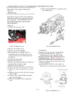
11) Remove the fuel filter.
Fig.2-10 Fuel filter
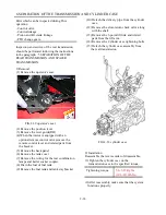
12) Remove the oil cooler and radiator on the
axle bracket
13) Remove the battery and battery bracket.
14) Remove the two hoses for the power
steering system.
15) Remove the mounting bolts of the right
hand pivot metal(support) ahead of time.
16) At this stage,the power steering unit can be
removed by disconnecting both right-hand
and left hand tie-rods and removing the unit
mounting bolts.
Note:
When the pipes related to the hydraulic system
are removed,their openings should be covered
with plastic caps or the like to keep out dust or
other foreign matter.
Fig.2-11 Net of Oil cooler
Note:
Here the Net of Radiator can be removed as an
assembly.
Fig.2-12 Battery and Battery Bracket
2-7
Summary of Contents for T233 HST
Page 14: ...1 11...
Page 15: ...1 12...
Page 22: ...SECTION 3 GEAR TRAIN DIAGRAMS FIG 1 3 GEAR TRAIN DIAGRAM 1 19...
Page 33: ...SECTION 2 OPERATION CHART FOR DISASSEMBLY AND REASSEMBLY BY MAJOR BLOCKS 2 4...
Page 60: ...3 HST main pump case 4 5...
Page 64: ...6 Hydrostatic system schematic 4 8...
Page 100: ...3 Rear transmission case 5 15 Fig 5 23...
Page 121: ...Power Train Diagram Fig 5 60 5 36...
Page 210: ...SECTION 6 WIRING DIAGRAM 10 12...


