3. INSPECTION OF EACH PART
1) Inspection of the cleaner body
(1) Check the cleaner exterior for cracks,
deformation,or damage and repair or replace
if necessary.
(2) Check each packing for fatigue or damage
and replace if necessary.
2) Inspection of rubber hoses
Check the rubber hoses for fatigue or damage
and replace if necessary.
3) Inspection of the paper element
Note:
Especially note the glue portions of the paper and
metal parts.
4. CLEANING THE AIR CLEANER
Clean the air cleaner after 100 hours of operation or
less depending on conditions in the following
manner.
1) When the air cleaner is cleaned or the element is
replaced,dust accumulated inside the air cleaner
body should be removed with a cloth.As inhaled
dust causes engine wear,remove a dust
accumulated inside the inlet pipe,the rubber hose
which connects in the inlet pipe and the air
cleaner,the inlet manifold,and inlet port.
(1)When accumulated dust is dry.
-When removing the dust in the element,hold
the element by a hand and pat the side wall
with other hand.Never hit the element against
a stone or a concrete wall because that might
cause its side wall to peel off.
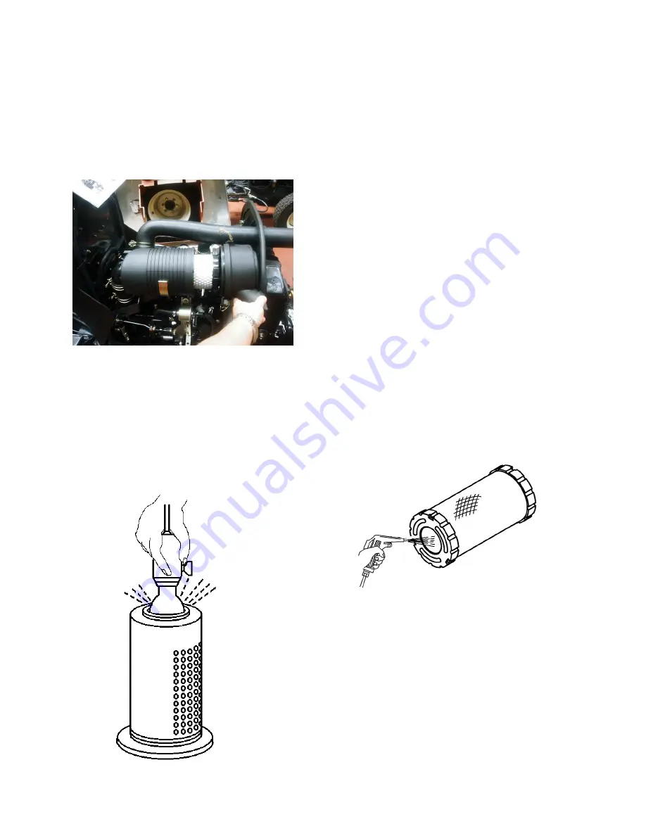
-apply compressed air from inside of the element to
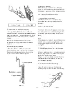
3) Inspection of the paper element
To check the element for damage, Dry it
sufficiently after washing and put an electric
bulb in to the element and look for damage.
Fig. 3-12 Element check
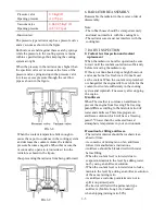
-apply compressed air from inside of the element to
blow dust off while turning the element by hand.
Fig.3-13 Element
Note:
The compressed air to be applied should not
have a pressure of
more than 7
㎏
/
㎠
(99.6psi)
Maintain sufficient distance between the air gun
and the element.
(2)When accumulated dust is oily.
-Use a solution of TC 101 element detergent
or the quality household neutral detergent.
Leave the element in the solution for
approximately 30 minutes and then wash it by
dipping it in and out of the solution.
3-9
Summary of Contents for T233 HST
Page 14: ...1 11...
Page 15: ...1 12...
Page 22: ...SECTION 3 GEAR TRAIN DIAGRAMS FIG 1 3 GEAR TRAIN DIAGRAM 1 19...
Page 33: ...SECTION 2 OPERATION CHART FOR DISASSEMBLY AND REASSEMBLY BY MAJOR BLOCKS 2 4...
Page 60: ...3 HST main pump case 4 5...
Page 64: ...6 Hydrostatic system schematic 4 8...
Page 100: ...3 Rear transmission case 5 15 Fig 5 23...
Page 121: ...Power Train Diagram Fig 5 60 5 36...
Page 210: ...SECTION 6 WIRING DIAGRAM 10 12...


