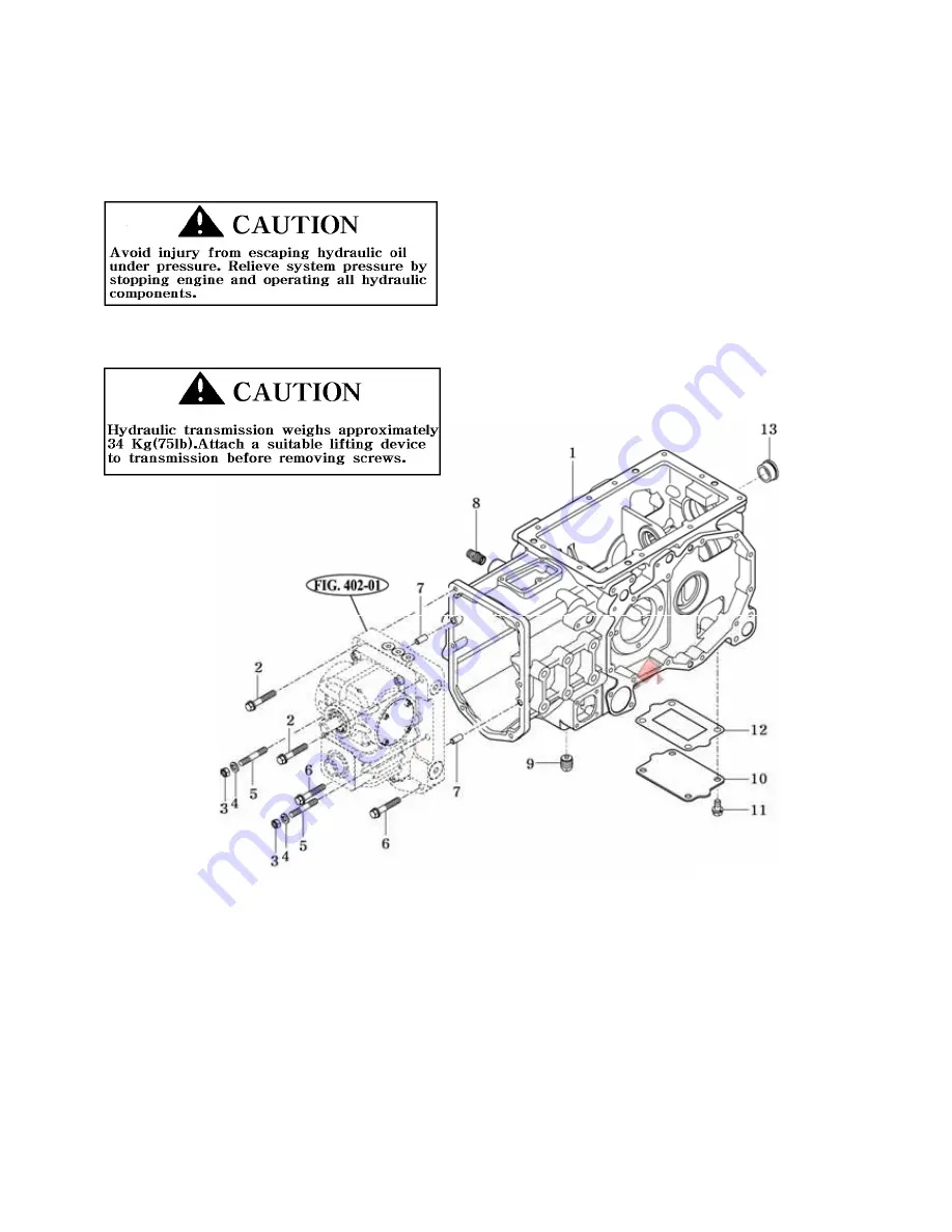
2. HYDRAULIC TRANSMISSION REMOVAL & INSTALLATION
Removal :
1.Park tractor on level surface.Stop engine and release hydraulic pressure by operating all controls.
2.Separate tractor engine and tunnel sections (See TRACTOR SPLITTING(FRONT).
3.Remove four bolts, two nuts, and two lock pins, and disconnect transmission forward
4. Note length and location of screws when removing.
NOTE : Oil may drain from the pump and motor unit after it is removed.Have a suitable container
ready to catch excess oil.
Installation : Installation is the reverse of removal.
- Clean flanges of transmission before applying sealant.
- Apply TB1215 sealant to flanges of transmission where it contacts the hydrostatic unit.
- Tighten the screws attaching transmission to hydrostatic unit.
IMPORTANT : If neutral adjustment locking screws was loosened, neutral adjustment procedure
must be performed.See “HYDROSTATIC PEDAL AND NEUTRAL ADJUSTMENT”
4-20
Summary of Contents for T233 HST
Page 14: ...1 11...
Page 15: ...1 12...
Page 22: ...SECTION 3 GEAR TRAIN DIAGRAMS FIG 1 3 GEAR TRAIN DIAGRAM 1 19...
Page 33: ...SECTION 2 OPERATION CHART FOR DISASSEMBLY AND REASSEMBLY BY MAJOR BLOCKS 2 4...
Page 60: ...3 HST main pump case 4 5...
Page 64: ...6 Hydrostatic system schematic 4 8...
Page 100: ...3 Rear transmission case 5 15 Fig 5 23...
Page 121: ...Power Train Diagram Fig 5 60 5 36...
Page 210: ...SECTION 6 WIRING DIAGRAM 10 12...


