Introduction & Description
TRACTOR AN INTRODUCTION
The word, ’Tractor’ has been derived from ‘Traction’ which means pulling.
A Tractor is required to pull or haul an equipment, implement or trolley which are coupled to the Tractor
body through suitable linkage. A Tractor can also be used as a prime mover as it has a power outlet
source which is also called Power Take or PTO shaft.
In this book the operating, maintenance and storage instructions for all models of
TYM
Diesel Tractors
has been complied. This material has been prepared in detail to help you in the better understanding of
maintenance and efficient operation of the machine.
If you need any information not given in this manual, or require the services of a trained mechanic,
please get in touch with the
TYM
Dealer/Distributor in your locality. Dealer/Distributors are kept
informed of the latest methods of servicing Tractors. They stock genuine spare parts and are backed by
the Company’s full support.
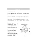
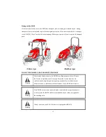
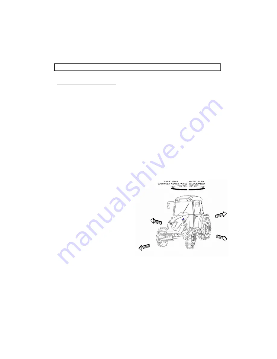
Through this manual. The use of the terms LEFT,
RIGHT, FRONT and REAR must be understood,
RIGHT, FRONT and REAR must be understood,
to avoid any confusion when following the
introductions. The LEFT and RIGHT means left
and right sides of the Tractor when facing
forward in the driver’s seat, Reference to the
FRONT indicates the radiator end of the Tractor,
while the REAR, indicates the drawbar end
(illustration E)
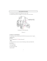
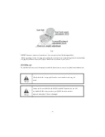
When spare parts are required, always specify
the Tractor and engine serial number when
ordering these parts.(See illustration A).This will
facilitate faster delivery and help ensure that the
correct parts for your particular Tractor is
received. The tractor serial number is punched
on a plate attached to the left hand side of the
engine body (illust.A),For easy reference, we
suggest you to write the number in the space
provided in the owner’s personal data.
8
illustration E
( Front, Rear,Left,Right Portion)
Summary of Contents for T603
Page 2: ......
Page 34: ......
Page 82: ......
Page 105: ...T603 CABIN WIRING DIAGRAM A3 103 ...
Page 106: ......
Page 107: ...T603 ROPS WIRING DIAGRAM A3 105 ...
Page 108: ......
Page 109: ...T603 WIRING DIAGRAM FOR POWER SHUTTLE If equipped 105 ...
Page 110: ......
Page 111: ...WIRING DIAGRAM 107 ...
Page 112: ...CABIN WIRING DIAGRAM 108 ...
Page 113: ...CABIN WIRING DIAGRAM 109 ...
Page 115: ... T603 POWER TRAIN 111 ...
Page 116: ... T603 POWER TRAIN FOR POWER SHUTTLE If equipped 111 ...
Page 118: ...DATE TRACTOR HOURS NATURE TYPE OF REPAIR SERVICE CARRIED OUT SERVICE RECORD 113 ...
Page 120: ...PART REPLACEMENT RECORD DATE PART DESCRIPTION QTY COST DATE PART DESCRIPTION QTY COST 115 ...
Page 121: ...T603 Operator s Manual for Tractors Code No 1995 940 002 1 Printed on August 2008 3rd Edition ...


