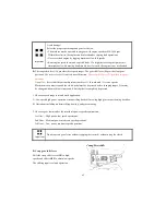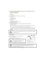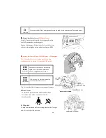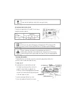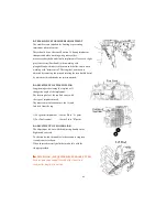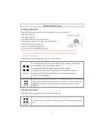
First select the specified speed for the PTO by using the PTO shifter on the LHS, below the driver seat.
PTO
ON/OFF
Switch
PTO
Control
Switch
Clutch Pedal.
Hydraulic
Position
Control Lever.
PTO
Monitor
Lamp on the
dash panel
PTO SHAFT
On
Manual
Mode
Either pressed
or released
Either raised or
lowered
Glows
Rotates
On
Auto
Mode
Pressed
Either raised or
lowered
Blinks
Stationary
On
Auto
Mode
Either pressed
or released
Raised
Blinks
Stationary
On
Auto
Mode
Released
Lowered
Glows
Rotates
■
■
■
■
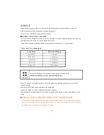
From the table above we learn about the safety features of the PTO. When the monitor on the dash
panel is blinking it indicates to the operator that the PTO is in the on position but temporarily not
rotating either because the clutch pedal is pressed or the implement is lifted off the ground or both.
The PTO will start rotating instantaneously when either the clutch pedal is released and/or the
implement is lowered to the ground.
■
■
■
■
The operator must use this blinking signal to clear the area around the tractor off
bystanders/onlookers as the rotating blades of certain implements can accidentally cause injuries to
the persons standing near the tractor.
■
■
■
■
The stopping of the PTO when the implement is lifted off the ground with the position control
prevents the damage to the implement or the PTO shaft.
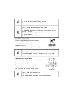
1.When the PTO control switch is in manual position the PTO does
not stop rotating even if the clutch pedal is pressed. If working on
hard soils,pavements with a rotary implement the PTO ON/OFF
switch must be put to the OFF position to stop the PTO from rotating , If
this is not done the rotating blades of the implement will push on the
hard ground below and in turn push the tractor toward causing accident
which can lead to serious injuries or death.
2. Extra precaution must be taken to clear the area of bystanders/onlookers when using PTO driven
implements. The rotating blades of the implements can cause serious injuries on contact. The
warning that is indicated by the blinking PTO monitor is to make the operator aware that the
PTO is in on position and will instantly start rotating if the clutch pedal is released or implement
is lowered or both.
3.In no case the specified rotating speeds indicated by the implement manufacturer be crossed as the
same can lead to serious damage to the tractor/equipment and can lead to serious injuries to
persons around.
38
Warning
Summary of Contents for T603
Page 2: ......
Page 34: ......
Page 82: ......
Page 105: ...T603 CABIN WIRING DIAGRAM A3 103 ...
Page 106: ......
Page 107: ...T603 ROPS WIRING DIAGRAM A3 105 ...
Page 108: ......
Page 109: ...T603 WIRING DIAGRAM FOR POWER SHUTTLE If equipped 105 ...
Page 110: ......
Page 111: ...WIRING DIAGRAM 107 ...
Page 112: ...CABIN WIRING DIAGRAM 108 ...
Page 113: ...CABIN WIRING DIAGRAM 109 ...
Page 115: ... T603 POWER TRAIN 111 ...
Page 116: ... T603 POWER TRAIN FOR POWER SHUTTLE If equipped 111 ...
Page 118: ...DATE TRACTOR HOURS NATURE TYPE OF REPAIR SERVICE CARRIED OUT SERVICE RECORD 113 ...
Page 120: ...PART REPLACEMENT RECORD DATE PART DESCRIPTION QTY COST DATE PART DESCRIPTION QTY COST 115 ...
Page 121: ...T603 Operator s Manual for Tractors Code No 1995 940 002 1 Printed on August 2008 3rd Edition ...

