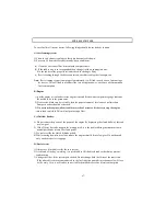
VENTILATION
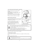
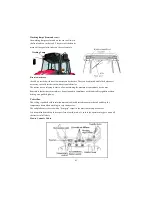
The ventilation unit is housed in the cab ceiling.
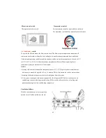
To switch it on and adjust it, turn the electrical fan switch to the desired speed.
The cab becomes slightly pressurized when the ventilation system is in operation, so that the fresh
air can enter only by way of the filter installed in the rear section of the cab roof.
The fan switch can be operated only after the ignition key is inserted.
The air flow can be regulated and directed by suitable positioning the air diffusers.
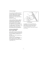
Air can be taken in fresh from outside or recirculated from within the cab by way of the relative
side inlets
Recirculation inlets fully closed:
air is taken in entirely from outside the cab through the rear grille and filtered through a paper
element positioned behind the grille.
N.B-it is very important that the air diffusers never be completed closed so as to allow for a steady
air flow.
To obtain a greater pressurization inside the cab, it is necessary to take the air from the outside,
therefore the inside air recirculatiing grille should be fully closed.
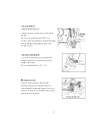
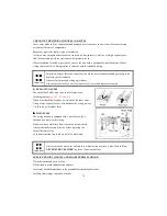
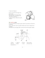
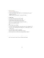
Working lamp switch
The front and rear working lights are ON when
push the button.The work light indicator lamp on
the instrument cluster will illuminate.
Wiper control switch
ON switch
-Wind screen wiper operation
-Continuous pushing button operates wiper and
washer pump
OFF switch
-Wind screen wiper Off and operates washer pump
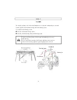
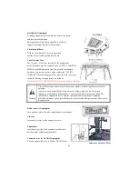
Windscreen Washer tank
Check the level of windscreen washer fluid in the
plastic reservoir located at the front of the radiator
During winter,it is advisable to add a suitable
antifreeze
or methyl alcohol to the windscreen washer fluid.
Interior Lamp
Push the button to light on
And push it again to light off
84
Summary of Contents for T603
Page 2: ......
Page 34: ......
Page 82: ......
Page 105: ...T603 CABIN WIRING DIAGRAM A3 103 ...
Page 106: ......
Page 107: ...T603 ROPS WIRING DIAGRAM A3 105 ...
Page 108: ......
Page 109: ...T603 WIRING DIAGRAM FOR POWER SHUTTLE If equipped 105 ...
Page 110: ......
Page 111: ...WIRING DIAGRAM 107 ...
Page 112: ...CABIN WIRING DIAGRAM 108 ...
Page 113: ...CABIN WIRING DIAGRAM 109 ...
Page 115: ... T603 POWER TRAIN 111 ...
Page 116: ... T603 POWER TRAIN FOR POWER SHUTTLE If equipped 111 ...
Page 118: ...DATE TRACTOR HOURS NATURE TYPE OF REPAIR SERVICE CARRIED OUT SERVICE RECORD 113 ...
Page 120: ...PART REPLACEMENT RECORD DATE PART DESCRIPTION QTY COST DATE PART DESCRIPTION QTY COST 115 ...
Page 121: ...T603 Operator s Manual for Tractors Code No 1995 940 002 1 Printed on August 2008 3rd Edition ...


