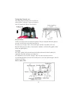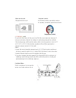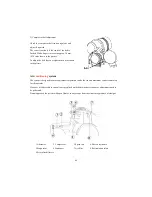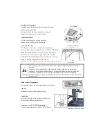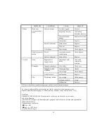
SYSTEM CONFIGULATION
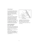
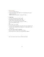
1.The heating system consist of two units:
1-Electric heater and blower unit installed behind roof console.
2-Power supplying set, consisting of an auxiliary alternator located front of the engine
and driven by a belt directly linked to the engine pulley.
If the air does not come out from the diffusers right away as soon as the system is started, turn
off immediately and identify the fault.
N.B-Never turn on the heating system when working in dusty environments.
87
Summary of Contents for T603
Page 2: ......
Page 34: ......
Page 82: ......
Page 105: ...T603 CABIN WIRING DIAGRAM A3 103 ...
Page 106: ......
Page 107: ...T603 ROPS WIRING DIAGRAM A3 105 ...
Page 108: ......
Page 109: ...T603 WIRING DIAGRAM FOR POWER SHUTTLE If equipped 105 ...
Page 110: ......
Page 111: ...WIRING DIAGRAM 107 ...
Page 112: ...CABIN WIRING DIAGRAM 108 ...
Page 113: ...CABIN WIRING DIAGRAM 109 ...
Page 115: ... T603 POWER TRAIN 111 ...
Page 116: ... T603 POWER TRAIN FOR POWER SHUTTLE If equipped 111 ...
Page 118: ...DATE TRACTOR HOURS NATURE TYPE OF REPAIR SERVICE CARRIED OUT SERVICE RECORD 113 ...
Page 120: ...PART REPLACEMENT RECORD DATE PART DESCRIPTION QTY COST DATE PART DESCRIPTION QTY COST 115 ...
Page 121: ...T603 Operator s Manual for Tractors Code No 1995 940 002 1 Printed on August 2008 3rd Edition ...

