

Doc
No.
FM0589
issue
A
Page
10
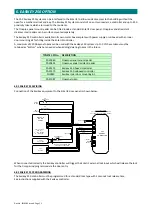
5.
LOCK
RELEASE
The
choice
of
electric
lock
release
lock
is
left
to
the
installer
so
the
most
appropriate
type
and
mounting
kit
can
be
obtained
for
each
installation.
The
lock
chosen
should
operate
from
12V
DC
for
direct
connection
to
the
Entel
i2
door
panel,
if
an
AC
lock
or
higher
voltage
DC
lock
is
used
then
a
separate
PSU
will
be
required.
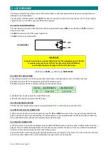
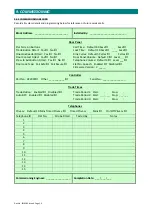
5.01
12V
DC
LOCK
CONNECTION
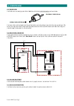
The
lock
release
is
connected
directly
across
the
door
panel
Lock
Supply
(
LKSP
)
and
Lock
Return
(
LKRT
)
terminals
using
1.0mm
cable.
The
LKSP
terminal
is
a
+12V
DC
supply
fused
at
1A.
The
LKRT
terminal
is
a
switched
0V.
LKRT
DC
LOCK
ONLY
LKSP
IMPORTANT
A
reverse
bias
diode
or
a
varistor/MOV
must
be
fitted
directly
across
all
DC
lock
terminals
to
prevent
back
emf
from
the
lock
coil
causing
malfunction
and
possible
long
term
damage
to
the
Entel
i2
door
panel.
Diode
Type:
1N4001
or
MOV
Type:
GNR07D330K
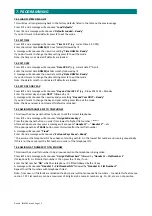
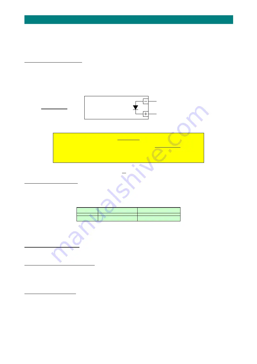
5.02
LOCK
TYPE
LINK
SETTING
A
link
setting
is
provided
on
the
door
panel
board
to
choose
a
standard
(fail
secure)
or
fail
safe
lock
type.
With
LK1
in
position
“
A
”
0V
is
applied
during
the
lock
release
period.
With
LK1
in
position
“
B
”
0V
is
removed
during
the
lock
release
period.
LINK
No.
LINK
POSITION
'A
'
LINK
POSITION
'B'
LK1
standard
lock
fail
safe
lock
A
standard
lock
requires
power
to
unlock
(fail
secure).
A
fail
safe
lock
requires
power
to
lock
(fail
open).
5.03
LOCK
RELEASE
DURATION
The
time
the
lock
release
remains
open
is
programmable
from
1
to
99
seconds,
see
section
7.09.
5.04
PRESS
TO
EXIT
(PTE)
CONNECTION
A
N/O
press
to
exit
button
can
be
connected
across
the
0V
and
EXLK
terminals
in
the
door
panel
to
override
the
lock
release
and
allow
egress
from
the
building.
For
added
safety
it
is
recommended
that
the
PTE
button
N/C
contacts
are
also
connected
in
series
with
the
lock
supply
wiring
on
fail
safe
locks.
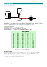
5.05
TAILGATE
CONNECTION
A
N/C
door
contact
should
be
connected
across
the
0V
and
T/G
terminals
in
the
door
panel
to
detect
when
the
door
is
opened.
This
will
automatically
terminate
the
lock
timer
2
seconds
after
the
door
re
‐
closes
and
reduce
the
likelihood
of
other
visitors
entering
during
the
same
lock
release
period.
The
contact
is
also
used
to
illuminate
the
telephone
LED’s
green
to
indicate
“door
open”.
If
a
door
contact
is
not
fitted
then
T/G
must
be
linked
to
0V
and
the
telephone
door
open
LED’s
will
not
function.


