
Doc
No.
FM0589
issue
A
Page
18
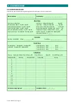
9.
COMMISSIONING
9.01
FULL
SYSTEM
TEST
Press
the
door
panel
button
to
call
the
first
flat
number
The
telephone
in
the
flat
should
ring
and
a
message
should
announce
“
Calling
Flat
XX
”
Check
the
flat
number
announced
is
the
same
as
that
engraved
on
the
door
panel
button
When
the
handset
is
lifted
the
telephone
ring
and
door
panel
message
should
stop
Confirm
the
flat
number
called
is
the
telephone
answered
Check
two
way
speech
between
door/flat,
volume
level
OK
with
no
feedback
When
the
telephone
button
is
pressed
a
message
should
announce
“
Door
Open
–
Please
Enter
”
Check
the
door
lock
is
released
Check
the
speech
cancels
when
the
telephone
is
hung
‐
up
Check
the
door
re
‐
locks
2
seconds
after
it
has
closed
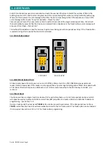
Press
the
telephone
button
to
select
privacy
mode
–
the
LED
will
illuminate
red
Call
the
same
flat,
the
telephone
should
not
ring
and
a
message
should
announce
“
Sorry
–
Not
Available
”
Press
the
telephone
button
again
to
turn
privacy
mode
off
–
the
LED
will
go
out
Call
the
same
flat,
after
the
call
is
answered
hang
‐
up
without
releasing
the
lock
Check
the
call
cancels
and
a
message
should
announce
“
Sorry
–
Access
Denied
”
Repeat
above
tests
for
each
flat.
Wedge
the
entrance
door
open
and
check
the
LED’s
are
illuminated
green
on
ALL
telephones
If
not
in
a
trade
time
period
the
door
panel
TRADE
button
should
not
function
Enter
program
mode
and
reset
the
system
time
to
within
a
trade
time
period.
Exit
program
mode.
Press
the
door
panel
TRADE
button,
a
message
should
announce
“
Door
Open
–
Please
Enter
”
and
the
door
lock
will
release.
Return
to
the
program
mode
and
reset
the
correct
time.
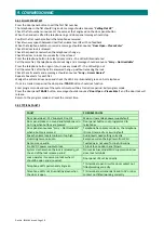
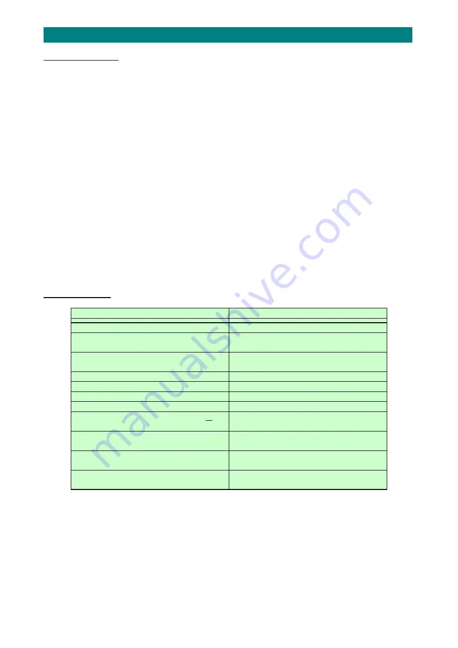
9.02
TYPICAL
FAULTS
FAULT
POSSIBLE
CAUSE
Door
panel
dead
‐
12V
Supply
LED
not
lit
Mains
or
low
voltage
power
supply
fault
Door
panel
makes
no
sound
and
telephones
do
not
ring
when
buttons
are
pressed
Door
panel
buttons
not
programmed
to
telephones
Door
panel
announces
“
Sorry
–
Not
Available
”
when
a
button
is
pressed
Telephone
has
privacy
mode
on,
the
telephone
ID
is
set
incorrectly
or
a
wiring
fault
Speech
volume
levels
too
low
or
too
high
Audio
levels
need
setting
correctly
Humming
noise
on
audio
Excessive
current
being
drawn
from
PSU
Data
noise
on
audio
Twisted
pairs
not
used
for
line
A/B
wiring
No
12V
DC
power
supply
to
lock
1A
lock
fuse
on
door
panel
blown
System
crashes
when
the
lock
is
released
or
at
the
end
of
the
lock
release
period
No
reverse
bias
diode/MOV
suppression
across
door
lock
terminals
Lock
operates
in
reverse
(i.e.
locks
when
it
should
be
open
and
vica
‐
versa)
Door
panel
LK1
set
incorrectly
Telephone
LED’s
permanently
lit
green
T/G
terminal
open
circuit
or
door
contact
not
fitted/working
correctly
Telephone
LED’s
not
illuminating
green
when
the
door
is
open
T/G
terminal
permanently
linked
to
0V
or
door
contact
not
fitted/working
correctly


