
Doc
No.
FM0589
issue
A
Page
3
RELEASE
LOCK
1.00mm PAIR
PTE
BUTTON
CONTACT
DOOR
1 PAIR
1 PAIR
2.5mm EARTH
4 PAIR (LINE & POWER)
OPTION 2 (DAISY CHAIN)
1 PAIR TO EACH FLAT
CONNECTED IN PARALLEL
MAX 15 TELEPHONES
DOOR PANEL
OR
1 PAIR
240V AC
MAINS SUPPLY
ENTEL i2
TELEPHONE
ENTEL i2
CONTROLLER
ENTEL i2
EXIT
6
7
8
4
5
3
1
2
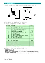
PRESS FLAT NUMBER REQUIRED
WAIT FOR ANSWER
SPEAK INTO DOOR PANEL
ENTER WHEN LOCK IS RELEASED
TO PAC
CONTROLLER
(OPTIONAL)
6 CORE
7/0.2mm
MAX 15 TELEPHONES INDIVIDUALLY
CONNECTED TO THE CONTROLLER
OPTION 1 (STAR)
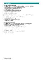
1.
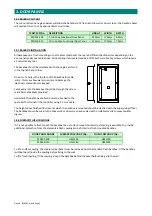
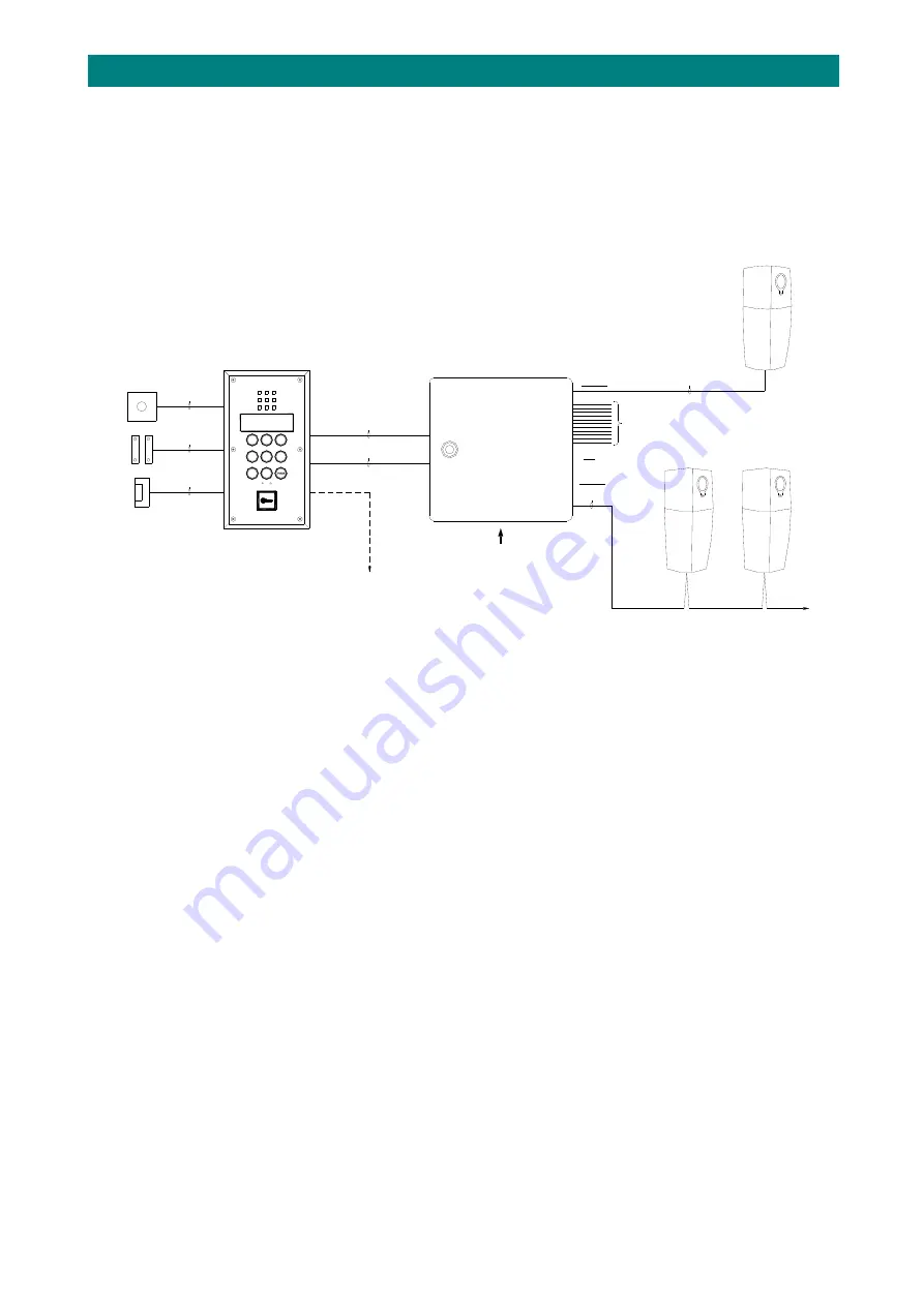
OVERVIEW
The
Entel
i2
Functional
Door
Entry
system
is
designed
to
comply
with
most
Local
Authority’s
specifications
for
buildings
with
up
to
15
flats
and
1
entrance
door.
Door
panels
are
vandal
resistant
stainless
steel
with
engraved
operating
instructions
and
a
flush
mounting
backbox.
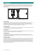
The
controller
includes
a
low
voltage
power
supply
and
a
termination
board
housed
in
an
IP65
lockable
enclosure.
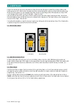
The
telephone
handsets
have
a
single
pushbutton
for
lock
release
or
privacy
and
a
single
LED
to
indicate
privacy
mode
or
door
open.
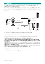
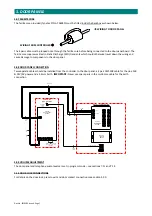
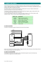
A
typical
installation
requires
2
separate
cables
between
the
door
panel
and
the
controller;
1
x
4
pair
0.5mm
CW1308
BT
spec
(Line
&
Power
Connection)
1
x
2.5mm
Earth
If
a
Oneprox
reader
is
fitted
in
the
door
panel
then
an
additional
6
core
7/0.2
cable
will
be
required
to
the
PAC
Easikey
controller.
Note,
door
panel
backboxes
and
fascias
must
be
bonded
to
the
spare
Mains
Earth
terminal
in
the
controller
using
a
2.5
mm
2
cable.
Cable
length
to
a
door
panel
should
not
exceed
150
metres.
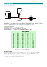
Telephones
are
connected
using
a
1
pair
CW1308
spec
cable,
they
can
be
individually
wired
back
to
the
controller
(star
formation)
or
looped
from
flat
to
flat
(daisy
chain
formation).
Maximum
cable
length
to
a
telephone
should
not
exceed
200
metres.
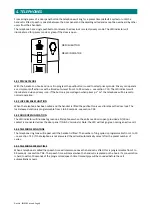
A
12V
DC
fail
safe
or
fail
secure
lock
release
can
be
is
connected
to
the
door
panel.
Always
ensure
a
protection
diode
or
MOV/varistor
is
fitted
directly
across
the
lock
terminals
to
prevent
voltage
transients
causing
damage
to
the
door
panel
electronics.
Maximum
lock
current
=
1A.
A
N/C
door
contact
can
be
connected
to
the
door
panel.
This
will
terminate
the
lock
release
time
after
the
door
has
been
opened/closed
and
illuminate
all
telephone
LED’s
green
if
the
door
is
left
open.
A
N/O
press
to
exit
button
can
be
connected
to
the
door
panel,
this
will
release
the
door
lock
and
allow
persons
to
exit
the
building.
See
Tynetec
Drg
No.
ZE200I
for
detailed
wiring
connections.


