

Doc
No.
FM0589
issue
A
Page
4
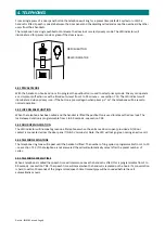
A
A
A00464
W00576
15V/60W SMPSU
TO 13.75V
SET OUTPUT
BOARD
TERMINATION
B
A
B
91
0
CON14
CON15
B
2
1
B
A
CON6
CON7
15
7
CON12
CON20
12V
CON1
PSU
IN
P
U
T
0V
12V
A
11
B
CON16
12
B
A
CON17
CON4
CON2
0V
CON3
0V
12V
CON19
13
B
A
B
CON18
14
A
B
A
3
B
CON8
4
A
B
CON9
CON11
5
B
A
B
CON10
6
B
A
CON5
LI
N
E
B
A
B
A
A
CON21
8
A
A
B
CON13
BAT +
BAT -
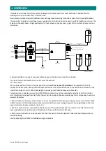
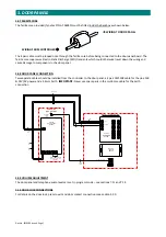
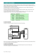
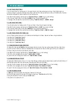
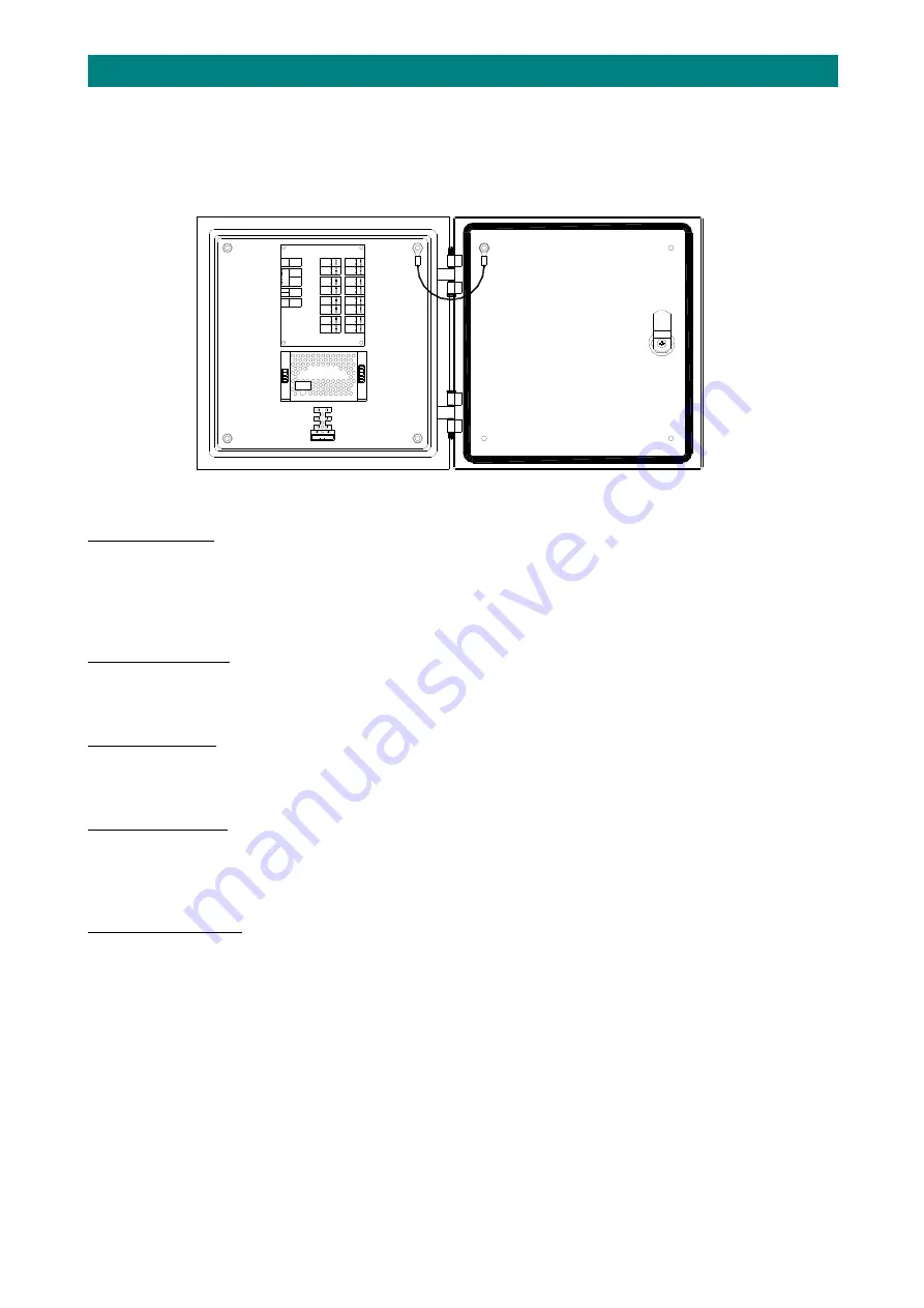
2.
CONTROLLER
The
Entel
i2
controller
(Tynetec
P/No.
ZE200I)
is
housed
in
a
300x300x150mm
(HxWxD)
IP65
lockable
enclosure.
This
includes
a
fused
mains
termination
block,
a
low
voltage
switch
mode
power
supply
unit
and
a
termination
board.
The
controller
can
connect
up
to
15
telephones
and
1
door
panel.
Leads
are
provided
for
an
optional
12V
2.8Ah
rechargeable
battery.
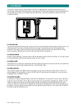
2.01
INSTALLATION
The
controller
should
be
located
in
a
dry,
secure
area
which
is
easily
accessible
for
termination
and
future
service.
The
cable
entry
plate
is
normally
on
the
bottom
with
the
door
hinges
on
the
right
hand
side.
The
backplate
can
be
inverted
if
it
is
necessary
to
fit
the
enclosure
with
the
cable
entry
plate
on
the
top
and
hinges
on
the
left.
Always
ensure
proprietary
cable
glands
are
used
to
maintain
the
IP65
rating
of
the
enclosure.
2.02
EARTH
BONDING
All
door
entry
metalwork
eg.
controller
cabinet,
door
panel
backbox
&
fascia,
fireman’s
switches,
etc.
must
be
bonded
to
Earth
via
the
Mains
Earth
terminal
using
a
minimum
of
2.5
mm
2
cable.
2.03
MAINS
SUPPLY
The
240V
AC
mains
connection
should
be
taken
from
the
landlords
supply
and
terminated
in
the
fused
screw
terminal
block
provided
in
the
controller.
Replacement
fuse
=
20mm
3A
anti
‐
surge.
2.04
SMPSU
MODULE
The
controller
includes
a
15V/60W
switched
mode
power
supply
unit
which
has
been
factory
set
to
13.75V
DC
for
battery
charging.
This
can
provide
an
output
current
of
4.3A
with
solid
state
overload
protection
‐
there
are
no
user
replaceable
fuses
in
the
SMPSU
module.
2.05
BATTERY
STANDBY
An
optional
12V
2.8Ah
rechargeable
battery
(Tynetec
P/No.
F00040)
can
be
connected
to
maintain
normal
operation
in
the
event
of
a
mains
failure.
The
standby
power
requirement
of
a
typical
system
(excluding
lock
release)
is
approx
200mA,
therefore
the
actual
time
the
system
will
be
supported
by
the
battery
is
determined
mainly
by
the
lock
current.
A
protection
circuit
will
disconnect
the
battery
in
the
event
of
prolonged
mains
failure
to
prevent
damage
to
the
battery.
The
mains
supply
must
be
applied
first
to
energise
the
protection
circuit,
ie.
the
system
will
not
function
by
simply
connecting
the
battery
alone.


