
Doc
No.
FM0589
issue
A
Page
6
3.
DOOR
PANELS
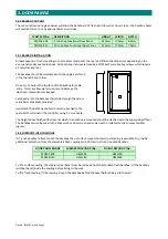
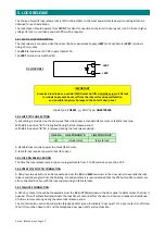
3.04
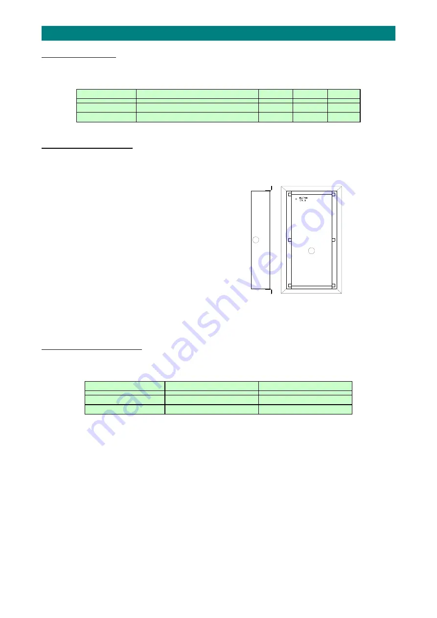
BACKBOX
CUT
‐
OUT
The
cut
‐
out
dimensions
given
below
will
allow
the
backbox
to
fit
flush
into
the
wall
or
door
screen
‐
the
backbox
bezel
will
overlap
this
cut
‐
out
by
approx
10mm
on
all
sides.
TYNETEC
P/No.
DESCRIPTION
HEIGHT
WIDTH
DEPTH
ZSD201
‐
209
1
to
9
Way
Functional
Door
Panel
320mm
170mm
60mm
ZSD210
‐
215
10
to
15
Way
Functional
Door
Panel
415mm
170mm
70mm
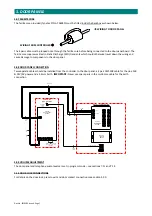
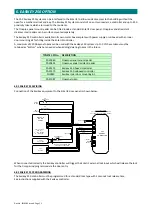
3.05
BACKBOX
INSTALLATION
All
backboxes
are
flush
mounting
with
a
stainless
steel
bezel,
there
are
2
different
backbox
sizes
depending
on
the
door
panel
model,
see
table
above.
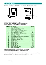
All
door
panel
fascias
are
fixed
by
6
off
M5x12mm
allen
key
screws
which
require
a
3mm
allen
key
tool.
The
backbox
should
be
orientated
with
the
single
Earth
stud
in
the
top
left
hand
corner.
Do
not
cut
a
hole
in
the
top
face
of
the
backbox
for
cable
entry
‐
this
may
allow
water
to
enter
and
damage
the
electronic
components
or
keypad.
Cable
entry
into
the
backbox
should
be
through
the
side
or
rear
20mm
knockouts
provided.
Important:
the
backbox
and
fascia
must
be
bonded
to
the
spare
Earth
terminal
in
the
controller
using
2.5
mm
2
cable.
The
height
above
finished
floor
level
at
which
the
backbox
is
mounted
should
be
clarified
with
the
Supervising
Officer.
The
backbox
should
be
cut
into
the
brick
work
or
door
screen
and
sealed
with
a
suitable
mastic
to
prevent
water
ingress.
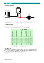
3.06
SURFACE/FLUSH
COWLINGS
If
it
is
not
possible
to
flush
mount
the
backbox
then
a
surface
mount
stainless
steel
cowling
is
available.
To
provide
additional
protection
from
the
elements
a
flush
cowling
can
be
fitted
to
a
flush
mounted
backbox.
DOOR
PANEL
RANGE
SURFACE
COWLING
P/No.
FLUSH
COWLING
P/No.
ZSD201
‐
209
HM1130
HM1100
ZSD210
‐
215
HM1140
HM1105
To
fit
a
surface
cowling;
the
stainless
steel
bezel
must
be
removed
from
the
standard
flush
backbox.
Fit
the
backbox
(without
bezel)
inside
the
cowling
before
fixing
to
the
wall.
To
fit
a
flush
cowling;
fit
the
cowling
around
the
backbox
behind
the
bezel
before
fixing
into
the
wall.


