

Doc
No.
FM0589
issue
A
Page
7
B
0V
12
V
T/
G
EXL
K
0V
LK
SP
LKRT
LINE
A
B
A
B
A
B
A
B
A
B
A
B
A
B
A
B
A
B
A
B
LINE
12V
12V
0V
0V
POWER
A00464
TERMINATION
BOARD
DOOR CONTACT, PRESS
TO EXIT & DOOR LOCK
TERMINALS
ZSD201-215
DOOR PANEL
BACKBOX
EARTH
POINT
1 PAIR
1 PAIR
2.5mm
EARTH
A
B
A
B
A
B
A
B
A
B
A
B
A
B
BOARD
DOOR PANEL
A00463
A
ENTEL i2 CONTROLLER
1 PAIR
1 PAIR
USE 4 PAIR
1 PAIR
1 PAIR
SMPSU
15V/60W
W00576
DOOR PANEL EARTH
12V
0V
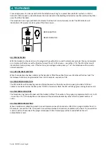
3.
DOOR
PANELS
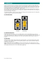
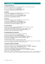
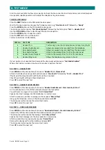
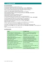
3.07
FERRITE
CORE
The
ferrite
core
provided
(Tynetec
P/No.
T06050)
must
be
fitted
inside
the
backbox
as
shown
below;
WIRING
TO
DOOR
PANEL
WIRING
FROM
CONTROLLER
The
4
pair
cable
must
be
looped
once
through
the
ferrite
core
before
being
connected
to
the
door
panel
board.
The
ferrite
core
suppresses
Electro
Static
Discharge
(ESD)
transients
which
could
otherwise
travel
down
the
wiring
and
cause
damage
to
components
in
the
door
panel.
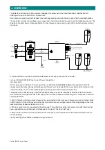
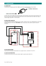
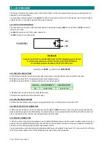
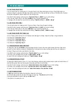
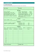
3.08
DOOR
PANEL
CONNECTION
Two
separate
cables
should
be
installed
from
the
controller
to
the
door
panel;
a
4
pair
CW1308
cable
for
the
Line
A/B
&
12V/0V
power
and
a
2.5mm
Earth.
IMPORTANT:
Never
use
spare
pairs
in
the
multi
‐
core
cable
for
the
Earth
connection.
3.09
VOLUME
ADJUSTMENT
The
door
panel
and
telephone
audio
levels
are
set
in
program
mode
–
see
sections
7.11
and
7.12.
3.10
DOOR
LOCK
CONNECTIONS
For
details
on
the
door
lock,
press
to
exit
and
door
contact
connections
see
section
5.00.


