Doc
No.
FM0589
issue
A
Page
9
LI
N
E
0V
TRIG
B
SET ID
DIL SWITCH
ST
R
O
BE
A
CONTROLLER POWER.
SPARE PAIR TO
LOCAL PSU OR
TRIG
0V
0V
12V DC
1 PAIR
ZSL055 STROBE
ENTEL i2 TELEPHONE
ENTEL i2 CONTROLLER
A00464
TERMINATION
BOARD
A
B
A
B
A
B
A
B
A
B
A
B
A
B
A
B
A
B
A
B
A
B
A
B
A
B
A
B
A
B
A
B
OPTIONAL
4.
TELEPHONES
4.06
TELEPHONE
CONNECTION
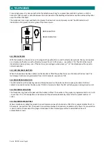
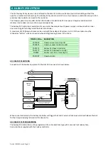
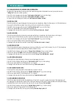
Each
telephone
can
be
individually
wired
to
the
controller
(star
formation)
using
a
1
pair
CW1308
twisted
pair
cable
or
up
to
15
telephones
can
be
wired
in
parallel
on
the
same
1
pair
cable
(daisy
chain
formation).
4.07
SETTING
TELEPHONE
ID
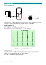
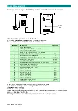
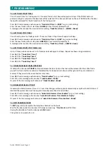
Each
telephone
has
a
4
way
DIL
switch
to
set
a
unique
ID.
Telephone
ID’s
must
run
sequentially
starting
from
1
through
to
15.
For
ease
of
programming
set
telephone
ID
1
in
the
lowest
flat
number
in
the
building.
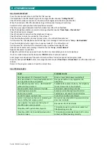
TEL
ID
DIL
SWITCH
NUMBER
1
2
3
4
1
ON
OFF
OFF
OFF
2
OFF
ON
OFF
OFF
3
ON
ON
OFF
OFF
4
OFF
OFF
ON
OFF
5
ON
OFF
ON
OFF
6
OFF
ON
ON
OFF
7
ON
ON
ON
OFF
8
OFF
OFF
OFF
ON
9
ON
OFF
OFF
ON
10
OFF
ON
OFF
ON
11
ON
ON
OFF
ON
12
OFF
OFF
ON
ON
13
ON
OFF
ON
ON
14
OFF
ON
ON
ON
15
ON
ON
ON
ON
DIL
switches
1
–
2
–
3
–
4
represent
binary
1
–
2
–
4
–
8
4.08
OPTIONAL
STROBE
A
strobe
light
for
the
hard
of
hearing
(Tynetec
P/No.
ZSL055)
can
be
connected
to
the
telephone
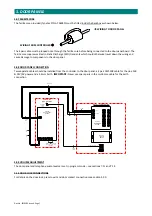
Trig
and
0V
terminals.
The
strobe
also
requires
connection
to
a
local
power
supply
(12VDC
@
200mA)
within
the
flat
or
connection
to
the
controller
AUX
12V/0V
supply
if
spare
cables
are
available.
IMPORTANT:
Only
1
strobe
can
be
connected
per
telephone.


