background image

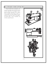
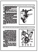
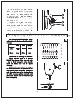
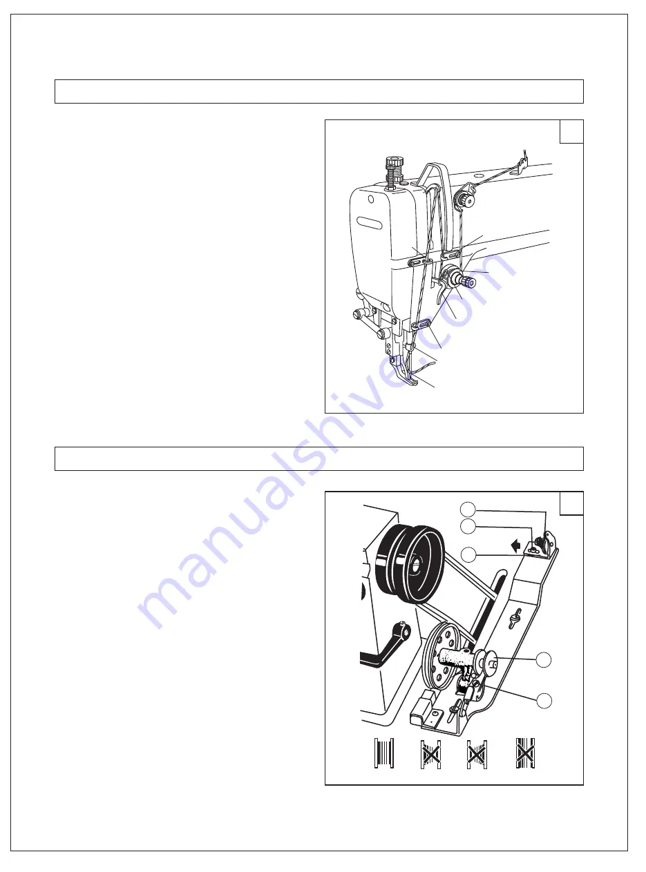
        When threading the needle thread, raise the needle 
bar to its highest position, lead the thread from the spool 
and pass it in the order instructed.                                  
         (1) Lead  the  thread  down  through  the  three-eye 

thread guide

 on the top.                                            

        (2) Pass  down   thru  the  left  hole  of  thread  re-
tainer

,  then  down   thru  the  lower  hole  of   thread

retainer

.                                                                          

        (3)Pass down thru between the two tension disc

          (4)Pass up thru the hook of thread take-up spring

.  

thru  thread  regulator  

, thru  thread  guide 

  and  up  

.

thru  the   hole  of  thread  take-up  lever


         (5) Down  thru  thread  guide  

,  

,  and  needle

bar  thread  guide 

,  then   pass   the   thread   from  the

left   thru  the  eye  of  needle

 , draw  out  the  thread

approx  100mm   from  the  needle  eye.                       
          When  drawing   the   bobbin   thread, hold  the tip
of    the    needle    thread    by   hand,  turn  the  balance
wheel  to  lower  the  needle  bar  and  then  to  lift  it  to
its   highest   position.  Pull  the  needle  thread  and then
the   bobbin   thread  is  drawn  up.  put   the   tips of the
needle   and   bobbin   thread  toward  front  under   the
presser foot.                                                                 


 .

  .

 .

 .

  .

    .  

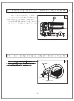
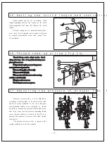
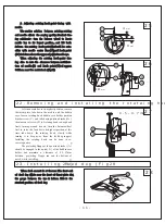
           The  wound  bobbin  thread  should   be  neat  and

tight.  If   not,   adjust   the   thread   tension  by   turning

tension  stud  thumb  nut  of  the  bobbin  winder  tension 

bracket (A). If  the  wound  bobbin  is  not  neat,  tension 

bracket(C)can be moved to be adjusted. When adjusting,

loosen  screw(B)first, then  move the bracket leftward or 

rightward  if  the thread is wound to one side as shown in 

Fig.15(6), move  the  tension  bracket  rightward, while if 

the thread is wound to  one  side  as  shown  in Fig.15(C),

move the tension  bracket  leftward  until  the  thread  is 

wound  neatly  as  shown  in  Fig.15(a),tighten screw(B).

          Note:  Nylon   or   polyester   thread   should   be 

wound with light tension. otherwise bobbin (D) might be 

broken or deformed.                                                      

          Don't overfill  the  bobbin,  because it make  its 

thread      loosening      down      from      the      bobbin.     The   

optimum  capacity  of   thread   will  fill  about  80%  of 

bobbin outside  diameter, and  this can  be  adjusted  by  

stop latch screw(E).                                                   

  .

   .

14.Winding adjustment (Fig 12)

13.Threading the needle thread (Fig 11)

12

11

-6-

1

2

3

5

9

10

11

4

8

6

7

A

d

B

C

E

11

Summary of Contents for GC0303

Page 1: ...0 3 GC 0 3 0 3 C X OPERATION INSTRUCTION PARTS MANUAL UPPER AND LOWER FEED MACHINE FOR HEAVY DUTY WITH THICK THREAD LOCKSTITCH SEWING UPPER AND LOWER FEED LOCKSTITCH SEWING MACHINE FOR MEDIUM AND HEAV...

Page 2: ...3391278 FAX 86 512 63391371 POST CODE 215223 Http www typicalwpchina com E mail export typicalwpchina com TYPICAL SEWING MACHINE WANPING MACHINERY CO LTD Please don t adjust and repair the machine by...

Page 3: ...e tension of needle thread and bobbin thread 21 Timing adjustment between the needle and the rotating hook 22 Installing and removing rotating hook 23 Installing feed dog 24 Feed dog horizontal adjust...

Page 4: ...Operation instruction Notice 1 Parts design is subject to change without notice 2 Only the professional can adjust and repair the machine except adjusting stitch length...

Page 5: ...justment should be done before operation a The optimum tilt angle of pedal with floor is approx 15 degree b Adjust the clutch of the motor so that clutch lever C and draw bar B run in line as Fig 6 th...

Page 6: ...the bobbin winder should be parallel with belt slit E of the table the fasten with two wood screw D A Oil amount Oil amount must be oiled according to the mark of drip pan Mark A is the highest situa...

Page 7: ...ughly the lift the presser foot and run at a low speed of 1000 1500spm observe the sparkling condition through oil window c as the lubrication is well keep the running test at the low speed about 30 m...

Page 8: ...ed in the range of five turns of Screw A Tightning for more Loosening for less Generally no adjustment is for oil pump When the machine is running at alow speed observe the oil screen If no oil splash...

Page 9: ...right hand in the direction of arrow shown in Fig 10 if it is tight it is left twisted con trarily it is right twisted The Needle is DP 17 20 24 GC0303CX DP 17 25 the needle number must be fitted for...

Page 10: ...the tips of the needle and bobbin thread toward front under the presser foot The wound bobbin thread should be neat and tight If not adjust the thread tension by turning tension stud thumb nut of the...

Page 11: ...stitch length and controlling 13 7 Thread take up section adopts woolen thread oiling after long time of use its function lost so re place with a new one Open the face plate remove the pressure screw...

Page 12: ...take up spring sew ing range of the thread take up spring tension of tension disc and the position of thread guide The normal sewing range of thread take up sping is 5 8mm For sewing light weight mat...

Page 13: ...case tension regulating screw with small plastic screw driver to make the bobbin thread get more tension Fig 21 thread take up spring C to zero and to turn ten sion stud B clockwise until spring C ju...

Page 14: ...l stitches as shown in Fig 20 d e adjustment can be made which reference to the above methods 1 Adjusting the position of needle bar Turn the balance wheel to locate the needle bar C at its lowest pos...

Page 15: ...cket screw C and take down position bracket A then loosen set screw D of rotating hook to keep hook freely turning around its axis turn the balance wheel first to raise the feed bar to its highest pos...

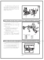
Page 16: ...Feed dog horizontal Adjustment Fig 30 31 12 30 29 25 Stitich length error adjustment Fig 31 Loosen Screw A and turn stitch length adjusting cam B Turn clockwise forward sewing stitch length enlarged r...

Page 17: ...d feed dog lift cam 2 Installing feed dog lift cam See Fig 33 3 Installing feed cam See Fig 34 26 Feed timing adjusting Fig 32 33 34 34 32 13 33 A B C C B Open the back side cover turn balance wheel b...

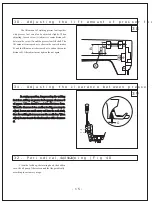
Page 18: ...d according to the differences of the friction coefficients of the friction coefficients of materials and the sewing pro cess Method Increase L the upper feed amount enlarged reduce L the upper feed a...

Page 19: ...B and the lift amount is decreased as to widen the center distance B After adjustment tighten the nut again In sewing operation for preventing the walking foot from striking on presser foot a proper...

Page 20: ...A A A Remove the throat plate clean off all the dust and lint on the slit of the feed dog A the installing the throat plate Clean off all the dust around the rotating hook A and clean the bobbin case...

Page 21: ...Parts Manual...

Page 22: ...3 4 6 7 8 8 8 9 10 10 10 11 11 5 12 13 14 15 16 17 18 19 20 21 22 23 24 25 26 27 28 29 30 31 32 33 34 36 38 39 40 35 36 37 41 42 43 44 45 46 47 48 49 50 58 5152 56 53 54 55 17 8 57 1 Machine Arm and...

Page 23: ...1 1 1 1 1 1 1 1 1 1 1 1 1 1 1 1 2 2 1 1 1 1 1 1 1 1 1 1 2 2 1 1 1 1 2 2 1 1 4 4 4 4 1 1 1 1 8 8 8 8 1 1 1 1 1 1 2 1 1 2 1 1 GB93 6 241WF1 002 75WF1 002 57 58 7WF4 030 13WF2 035 18 1 1 242WF1 001 Arm B...

Page 24: ...4 5 6 7 8 9 10 11 12 13 14 15 16 17 18 20 49 49 19 19 19 19 21 24 25 26 27 28 29 30 50 51 52 53 35 31 32 33 34 36 37 38 39 22 23 40 41 42 43 44 46 45 19 48 47 25 2 Arm Shaft and Vertical Shaft Needle...

Page 25: ...1 1 2 2 1 1 1 1 1 1 1 1 1 1 1 1 2 2 1 1 1 1 1 1 1 1 1 2 1 1 1 1 1 1 1 2 1 1 1 DP 17 23 GCO303CX 25 20 22T2 010 0303 0303CX No Part number Name Qt Remark Arm shaft Rubber plug Collar Screw Front bushi...

Page 26: ...d Dog Lift And Feed And Thread Loopin 1 2 3 4 5 6 7 8 9 10 11 12 13 14 15 16 17 18 19 20 21 22 23 24 25 26 27 28 30 31 32 33 34 35 36 37 38 39 29 49 41 42 43 44 45 46 46 48 11 12 13 46 10 41 30 40 40...

Page 27: ...1 1 1 3 3 1 1 1 1 1 1 1 1 1 1 1 1 1 1 1 1 3 3 1 1 1 1 1 1 1 1 1 1 1 1 1 1 1 1 1 1 2 2 2 2 1 1 1 1 1 1 1 1 4 4 1 1 1 1 GB894 1 15 GB93 6 22 22T4 001A1a2 0303 0303CX No Part number Name Qt Remark Feed...

Page 28: ...PUSH 1 2 3 4 5 6 7 8 9 1 0 1112 1 2 3 4 5 6 7 8 9 10 11 12 13 15 15 16 18 17 19 20 14 21 22 23 24 25 26 27 28 29 31 32 33 34 35 36 37 38 39 40 26 41 42 41 43 44 45 30 23 4 Feed Mechanism...

Page 29: ...1 1 1 1 1 1 1 1 1 1 1 1 1 1 1 1 1 1 1 1 1 1 1 1 1 1 1 1 2 2 3 3 1 1 1 1 1 1 1 1 2 2 1 1 2 2 1 1 1 1 1 1 1 1 1 1 1 1 2 2 1 1 1 1 1 1 1 1 O type ring 6 3 1 8G GB3452 1 92 24 33T2 030 A 0303 0303CX No P...

Page 30: ...1 2 3 4 5 6 7 8 9 10 11 12 13 14 15 16 17 18 19 20 9 21 22 23 26 28 29 30 21 25 27 25 24 31 32 5 Presser Foot...

Page 31: ...2 2 1 1 1 1 1 1 1 1 1 1 1 1 1 1 1 1 1 1 1 1 1 1 2 2 1 1 1 1 1 1 1 1 1 1 1 1 1 1 1 1 1 1 1 1 1 1 26 GB T848 4 0303 0303CX O type ring 4 5 1 8G GB3452 1 92 No Part number Name Qt Remark Presser foot li...

Page 32: ...10 11 12 13 14 15 16 17 67 18 19 20 66 1 1 21 22 23 24 25 26 27 28 29 30 31 32 33 34 64 65 37 38 39 40 26 21 35 36 41 42 43 44 45 47 48 61 49 50 51 52 53 54 55 56 57 58 59 60 46 54 55 55 55 19 9 63 62...

Page 33: ...1 1 1 1 1 1 1 1 1 4 4 1 1 2 2 1 1 1 1 1 1 1 1 2 2 1 1 1 1 2 2 1 1 1 1 1 1 1 1 1 1 2 2 1 1 1 1 1 1 1 1 1 1 1 1 2 2 1 1 1 1 1 1 1 1 1 1 1 1 1 1 1 1 1 1 1 1 1 1 2 2 3 3 1 1 2 2 1 1 1 1 1 1 GB T95 6 GB93...

Page 34: ...1 20 20 20 20 2 3 5 6 7 8 9 10 13 17 11 12 14 15 16 18 29 4 19 7 Oil Pump...

Page 35: ...3 1 2 1 2 1 1 1 1 1 1 1 4 GB T67 M3 10 30 GB T68 M3 10 GB93 4 0303 0303CX No Part number Name Qt Remark 7 Oil Pump Oil pump Big gear for oil pump small gear for oil pump Screw Cover for oil pump Adjus...

Page 36: ...1 2 3 4 5 6 7 8 9 10 11 12 13 14 15 16 17 18 19 20 21 23 24 25 26 27 28 29 30 31 32 33 34 35 36 37 38 39 40 41 31 22 8 Oil Reservoir and Accessories...

Page 37: ...1 1 1 1 1 1 1 1 2 2 2 2 2 2 2 2 1 1 5 5 1 1 4 3 1 1 1 1 1 1 4 4 2 2 32 GB T67 M4 8 GB T97 1 4 GB T67 M5 12 GB896 9 V type M39 DP 17 23 GC0303CX 25 GB5282 ST4 8 19 GB T95 6 14 GXJ 2C GB T5781 M6 12 M6...

Reviews: