Tyro Pyxis/Auriga 2F, 4F, 6F or 8F wireless remote control
Page
1
Tyro Remotes
Tel: +31-(0)546-588790
Bedrijvenpark Twente 1-B
Fax: +31-(0)546-579490
7602 KA Almelo
E-mail: info@tyroremotes.eu
The Netherlands
Website: www.tyroremotes.eu
Manual 868 MHz
Pyxis transmitter and Auriga receiver
Number of functions: 2, 4, 6 or 8,
ON/OFF.
Button functions
To activate the Pyxis tra
nsmitter: press and hold the “I” button for two seconds.
To deactivate the Pyxis tran
smitter: press and hold the “O” button for a second.
Mounting
To optimize the range of the Pyxis transmitter, it is recommended to place the antenna of the Auriga receiver as high
as possible and free from any metal objects. After connecting and mounting, it is recommended to test the device
before connecting it to the main powersource. Cable scheme is as follows:
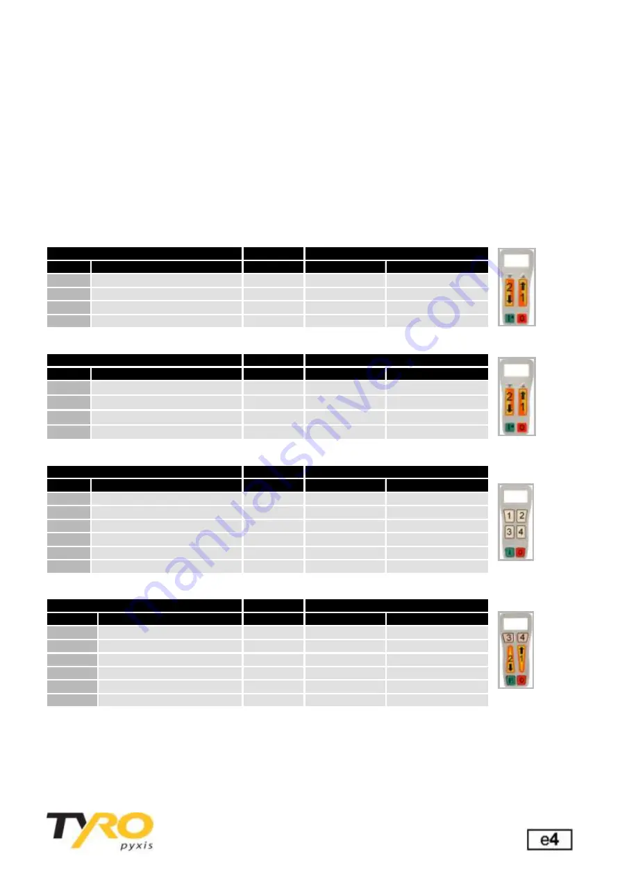
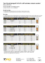
Pyxis transmitter 2F
Auriga receiver 3R PLC
Button
Relays
Inputs
Relays input
Relays output
“O”
1 deactivated
C 1
Q 1
“I”
1 activated
I1
C 1
Q 1
1↑
2
I2
C 2
Q 2
2↓
3
I3
C 3
Q 3
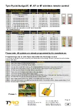
Pyxis transmitter 2F proportional
Auriga receiver 10R PLC +Analog
Button
Relays
Inputs
Relays input
Relays output
“O”
1 deactivated
C 1
Q 1
“I”
1 activated
I1
C 1
Q 1
1 ↑
2 +Analog on AO
I2
C 2
Q 2
2 ↓
3 +Analog on AO
I3
C 3
Q 3
Pyxis transmitter 4F
Auriga receiver 5R PLC
Button
Relays
Inputs
Relays input
Relays output
“O”
1 deactivated
C 1
Q 1
“I”
1 activated
I1
C 1
Q 1
1
2
I2
C 2
Q 2
2
3
I3
C 3
Q 3
3
4
I4
C 4
Q 4
4
5
I5
C 5
Q 5
Pyxis transmitter 4F proportional
Auriga receiver 10R PLC +Analog
Button
Relays
Inputs
Relays input
Relays output
“O”
1 deactivated
C 1
Q 1
“I”
1 activated
I1
C 1
Q 1
1
↑
2 +Analog on AO
I2
C 2
Q 2
2↓
3 +Analog on AO
I3
C 3
Q 3
3
4
I4
C 4
Q 4
4
5
I5
C 5
Q 5
All deliveries will be subject to our general sales conditions, available on demand or through
our website. Our products are certified for many applications. When mounting, always take
into account the applicable machine directives.


